Very nice Omishra !
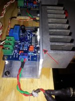
Nice layout. Good idea to put the tranformer under the capacitors.
I'm building a similar Turbo version 2, and keep that in mind...
Is the 0.55A bias the maximum the heatsinks can disipate? How hot do they get? Cause if I calculate 2.2A x 33V it is "only" 73Watts per sink, and it looks like they can do much more...
From where did you get the speaker ground to the connectors? From the amp-pcb or from the PSU?
Thank you everybody!
No, they are directly over the heatsink. Please see more pics here.
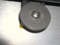
Are the transistors connected to the sink with an L bracket?
No, they are directly over the heatsink. Please see more pics here.
What did you use for insulators on the HS/transistors joint? They are very clean and appear as no spacer was installed. I've been looking at this.
FWIW, I have a roll of Kapton/polyimide tape left over from another project that I have used on my DCB1 buffer and Mini-A without issue (so far). I applied the tape to the part, used a small drill bit in my fingers to poke the hole for the screw, and trimmed the edges with a razor. I did not use any grease although perhaps I should consider that......
Attachments
Is there still an active Kerafol seller at diyA ?
(sharing a sheet with a few others, and ask a Euro sucker to send one over from the German RadioShack equivalent, is an alternate solution)
Well one can look at PM's and ask mates in the pub.
I got enoug to spare...

Not dissipates heat better the pads of aluminum oxide Fisher or Aavid?
I use Aavid and there is much improvement in temperatures ...
4180G Aavid Thermalloy | Mouser
I use Aavid and there is much improvement in temperatures ...
4180G Aavid Thermalloy | Mouser
I can buy the Kapton several places - I'll keep hunting for the Karatherm. Thanks
Hoi Bob, isn't this what you are looking for?
Warmtegeleidende folie Keratherm - Rood 86/82 Kerafol 86/82 (l x b) 100 mm x 100 mm Dikte 0,25 mm 6.5 W/mK in de Conrad online shop
I think that's what is mentioned in the article Jacco posted. (from EUVL)
BTW: nice article, Jacco ( and Patrick of course!)
Wow ! Lots of good choices. I'll check them out and report back on my selection. Still leaning toward a 1 mil thickness but that's not an absolute.
Thanks All
Edit: Don't know if I mentioned but another reason I am interested in the film (in a sheet) is use on larger surfaces. The pic is of a TDA7294 project that has a 3 1/4" X 1 1/2" common area. I'm still working on the liquid cooled discrete application which would require as much as a 4" X 11" contact pad. So cost also has to be considered. Simple grease might work but adding the thinnest film could assist the distribution over such a large area. Don't know yet.
Attachments
Last edited:
They are passing 10sec hand touch test with 0.6A/device bias. That was maximum possible for these heatsinks. But here now daytime temperature is 30deg Celcius. It will touch 40-45 during next couple of months. So keeping in mind that rise, I reduced bias to 0.55A/device.Is the 0.55A bias the maximum the heatsinks can disipate? How hot do they get? Cause if I calculate 2.2A x 33V it is "only" 73Watts per sink, and it looks like they can do much more...
Speaker grounds are taken from amp PCB. From PS ground(floating), wires go to earth ground isolator and amp board.From where did you get the speaker ground to the connectors? From the amp-pcb or from the PSU?
- Home
- Amplifiers
- Pass Labs
- Pictures of your diy Pass amplifier