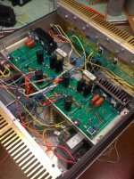
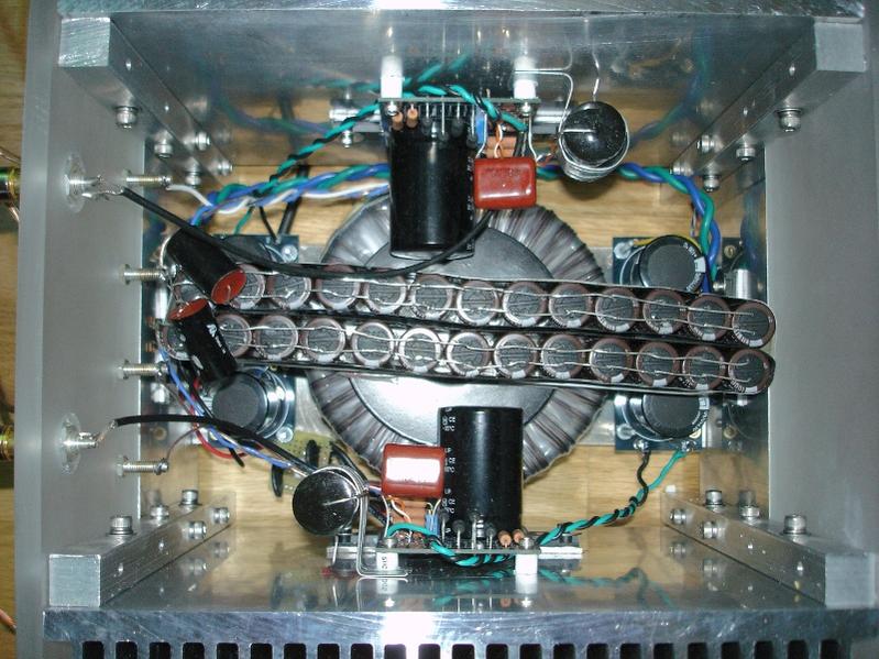
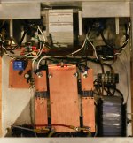
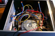
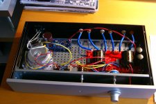
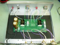
Here's the inside after a ton of wiring--yes, it's a bit busy.
I think you missed a wire there. I just got hungry lol
I think you missed a wire there. I just got hungry lol
Yes, don't forget the sauce.
Stateside, it is 1/8" plate for the back, bottom, front sub-panel and the same for the B1. The faceplates are 3/8" 6061 for the F5 and 1/4" for the B1. The B1 sides are 3" extruded aluminum T-track.What are you using 6mm Al plate?
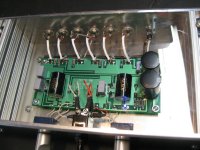
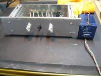
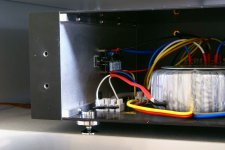
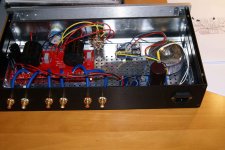
Got the B1 populated and wired. The little 24v. supply needs it's own little box and that will be next.
Attachments
Here's my F2, now F2-j
I think I'm linking to thumbnails, so if you care to see the larger pics, here's my post from last year when I built the amp.
http://www.diyaudio.com/forums/pass-labs/150652-finished-my-diy-f2-last-night-2.html#post1925588
I think I'm linking to thumbnails, so if you care to see the larger pics, here's my post from last year when I built the amp.
http://www.diyaudio.com/forums/pass-labs/150652-finished-my-diy-f2-last-night-2.html#post1925588
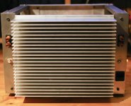
My F5
I take a guess and construct my f5 with one heatsink and a bunch of spare aluminium pieces and small heatsinks. I can bias it up to 1.3 amp, the mosffet is about 60 c.
I take a guess and construct my f5 with one heatsink and a bunch of spare aluminium pieces and small heatsinks. I can bias it up to 1.3 amp, the mosffet is about 60 c.
Attachments
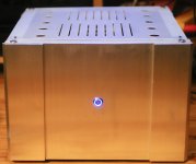
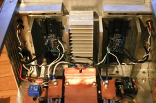
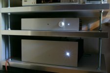
An other B1 and F5
After some months of building is this the result.
At a diy audio day in the Netherlands there were enthusiast comments.
Some has already started building
After some months of building is this the result.
At a diy audio day in the Netherlands there were enthusiast comments.
Some has already started building
Attachments
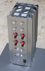

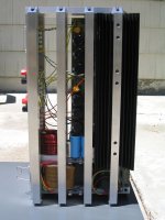
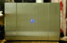
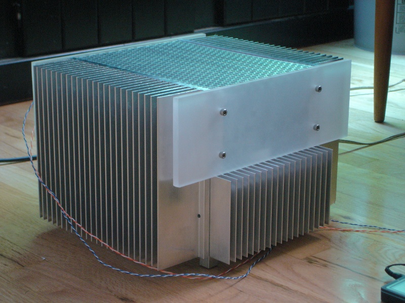
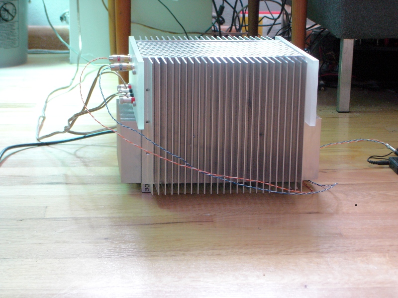
Hi Tosh,4x Zen: Designed in SolidWorks and made on CNC mills at De Anza College, Cupertino in 2007.
very original & impressive...

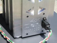
Side view a little bit unfinished...

4x Zen: Designed in SolidWorks and made on CNC mills at De Anza College, Cupertino in 2007.
Fugly!

4x Zen: Designed in SolidWorks and made on CNC mills at De Anza College, Cupertino in 2007.
Talk about ventilation...
Its an electric cheese grater.4x Zen: Designed in SolidWorks and made on CNC mills at De Anza College, Cupertino in 2007.
Its an electric cheese grater.
Only heaven know
Regards zeoN_Rider
looks very on topic to me
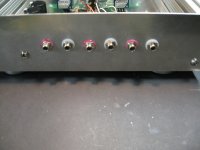
my B1(reclaimed Bogen mic amp case) and F5
jim

Hi Jim
Looks like you create a balance output from the unbalance....correct? how is this done and did the sound quality improve?
Attachments
4x Zen: Designed in SolidWorks and made on CNC mills at De Anza College, Cupertino in 2007.
Very impressive Tosh! I'm looking forward to what you're sculpting for your F5.
- Home
- Amplifiers
- Pass Labs
- Pictures of your diy Pass amplifier