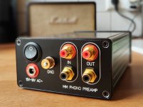
I have to assist, Schaeffer offers a very convenient way to make panels. The design software looks crude at the first look but you can do a lot of things very precisely. Considering front panels: they only offer silver colour when you want a 10mm thick panel. If you want black anodised Schaeffer limits the thickness to 4mm for whatever reasons.All the plates (top, rear, front) are made by Schaeffer AG in Germany https://www.schaeffer-ag.de/
You can download the designer software from the homepage in order to make your own designs; you can upload the finished designs directly from the software and a week or so later you have your plates.
I recently ordered this backpanels for Hammond 1455 extruded enclosure. Very pleased with the outcome. But if I would need small back panels like this in larger quantities, next time I would design them in KiCad and order PCBs for way less money.
Attachments
This is so cool. I have been experimenting with a similar approach but on a much smaller scale for IC voltage regulators that run high currents. Initially I was doing billet style tellurium copper point to point. The high cost of copper, especially telco, kept me from really exploring the process until I figured out a way to run the bulk of the circuit from aluminum and transition to copper right at the IC pads for soldering. The process is to mill telco pads to match the IC mask footprint, with a pin milled onto the backside of the pad. Then pin bores on the aluminum bus rails allow the pins to be press fit. The main issue is the galvanic imbalance. But my thinking is to mill these parts while submerged and keep them submerged during assembly. According to most literature on interfacing those metals, so long as the contacts are O2 free the galvanic process can be mitigated. The small scale stuff I was doing was a little hard to justify putting in the time for so I only made one attempt and haven't dialed in the process yet, but it definitely seems like a workable strategy. Beaucoup savings on copper for big stuff like you are doing!Most of the part were designed with 3D computer modeling, that I can simulate the assembly of all part and then put on cnc cut. More pictures of that part.
Happy to see you guy enjoying.")
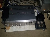
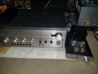
Newest member of the stable: the TDV with 2SK2087C outputs.
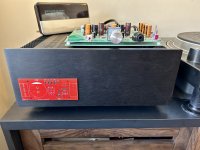
I’ve discovered a use for the extra odd PCBs we end up with after the minimum-of-5 orders. Slap it on the amp to identify it!
I’ve discovered a use for the extra odd PCBs we end up with after the minimum-of-5 orders. Slap it on the amp to identify it!
Attachments
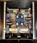
Your work are more complex in engineering than mine, which is just power amp casing.This is so cool. I have been experimenting with a similar approach but on a much smaller scale for IC voltage regulators that run high currents. Initially I was doing billet style tellurium copper point to point. The high cost of copper, especially telco, kept me from really exploring the process until I figured out a way to run the bulk of the circuit from aluminum and transition to copper right at the IC pads for soldering. The process is to mill telco pads to match the IC mask footprint, with a pin milled onto the backside of the pad. Then pin bores on the aluminum bus rails allow the pins to be press fit. The main issue is the galvanic imbalance. But my thinking is to mill these parts while submerged and keep them submerged during assembly. According to most literature on interfacing those metals, so long as the contacts are O2 free the galvanic process can be mitigated. The small scale stuff I was doing was a little hard to justify putting in the time for so I only made one attempt and haven't dialed in the process yet, but it definitely seems like a workable strategy. Beaucoup savings on copper for big stuff like you are doing!
View attachment 1110177
I think it just depends on how scarce or abundant your copper access is. Personally I'm even getting skittish with aluminum lol! Either way, just putting my "Cuprus Preservus" concept out there for the solid bar p2p style construction if the need arisesYour work are more complex in engineering than mine, which is just power amp casing.
I guess it's safe to post this, since the project has been running several days without problem. Its the Pass VFET 2SK60 O2 project. This is my first amp build, never built one before, so forgive sloppy execution. I did successfully build a Pass Korg B1 as my first DIY project.
I placed project as a tribute into a shelled out Sony TA 4650 chassis. Preamp section works with a small SMPS, but needs some TLC with cleaning etc. after 44 years. The Sony was the first commercial VFET amplifier from the day, I believe, followed by the other models and Yamaha B1 and B2.
I solved noise problems by cutting off the ground prong from the three ways to float the grounds and everything is silent. The chassis has two switched inputs. I have been using either the internal 4650 preamp or a Dot MkIII with a triode input and my favored orange globe 6dj8 as voltage gain amps. Heat was a concern, but it doesn't seem to run much hotter than low crikey. Turn on thump is pretty negligible.
The general sound is outstanding within it's impedance and power guard rails, and I have a few decades of hearing amps.
I have a few very nice amps, including Tokin SissySit type and the push pull Pass Vfet type, as well as various flea tube amps and a transmitting triode amp. However, using this little jobber on my midrange ribbon (6 ohm@greater than 93db efficient from 300 Hz to 7Khz), this VFET amp variant is already in danger of becoming a favorite. I have to let it run in for a while before checking bias and other tasks.
Attachments
Last edited:
I bought two 4650's on ebay for a couple of hundred apiece maybe 15 or 16 years ago, and used them for years as surround amps. They did their duty before fritzing out in various ways. I harvested the VFETs that were still good from these and a couple of other VFET chassis bought cheap.
I have no idea what obsessed me to do this, except that I have had VFET amps for a long time in various capacities. I am also surprised that to date the follow through was a form of success in spite of massive DIY clumsiness.
Now I am further shocked it is one of the best amps I have heard, not just a 10 watt DIY wonder. It's a worthy installment for the chassis.
Its pretty depressing to see such quality builds. Its almost professional. My stuff is aweful to look at. Albeit it works. I keep telling myself its just a hobby.Dual mono F6 in Deluxe 4U case. Thank you Papa and diyAudio store! View attachment 1111412
View attachment 1111413
View attachment 1111414
View attachment 1111415
View attachment 1111417
Ha! Brilliant application. Kind of Voyager-esque where, if I recall, they put a playback schematic on the golden LP they bolted to the side.I’ve discovered a use for the extra odd PCBs we end up with after the minimum-of-5 orders. Slap it on the amp to identify it!
It's that or use them as coasters for your martini.

Winter Blue! Beautiful.
*Truthfully that's iced tea, but it looks cool.
Why not both?It's that or use them as coasters for your martini.
*Truthfully that's iced tea, but it looks cool.
Attachments

What I value most is sound quality and bulletproof reliability; the rest is all window dressing. I do enjoy expressing via design aspects though.Its pretty depressing to see such quality builds. Its almost professional. My stuff is aweful to look at. Albeit it works. I keep telling myself its just a hobby.
With 6s 2800 I’m running it for about 1 hour. Voltage drop with lipos is so linear that it’s not a problem and the bias isn’t changing. I’ve also got tons of 6s 3300s that I’m staring to use. So, two of those for an evening of listening.
Lipo powered this thing sounds really amazing. Easily as good as any of my Pass or tube amps.
Lipo powered this thing sounds really amazing. Easily as good as any of my Pass or tube amps.
- Home
- Amplifiers
- Pass Labs
- Pictures of your diy Pass amplifier