I wanted to make another inputboard - sauce.....
lets switch

Dirk, your input switcher is great,
 ! That's the sort of creative implementation I envisioned when Mark and Jim first started posting about their M2x.
 I hope the switching works well. I'm sure everyone on the M2x thread will be eager to hear your impressions, as your ability to do A/B(/C) comparisons of input boards will be beyond that of any M2x I've seen yet.
Last edited:
I also made a post about this myself, stating six reasons why somebody might decide NOT to use a simple inrush current limiter in the primary: LINK
Thank you!
Think I will try the NTC resistor. I used it for connecting audio gnd to chassis gnd in previous project. I purchased some extras. They are a bit more "heavy duty" than CL-60 (can handle more current). If mains flickers worst thing that can happen is that fuse burns.
answer to tsmith 1315
Hello Tim,
thanks for your appreciation!
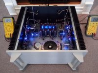
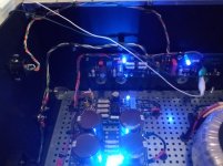
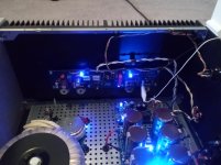
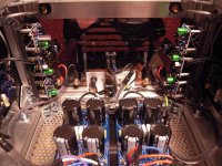
I was thinking: How much time I would need to change the inputboards?
I also had the idea to put the main pcb horizontally into the amp and the Mosfets
vertical to the heatsink.
At the moment I am working on the aluminum and acryl to cover the case/
frame. So I have easy access to the inputboards. But when it is closed
that switcher makes it easier and faster to change from one inputboard to the other. Good for comparisons.
But hey! - The design of the boards is perfect!
Cheers
Dirk
Hello Tim,
thanks for your appreciation!
I was thinking: How much time I would need to change the inputboards?
I also had the idea to put the main pcb horizontally into the amp and the Mosfets
vertical to the heatsink.
At the moment I am working on the aluminum and acryl to cover the case/
frame. So I have easy access to the inputboards. But when it is closed
that switcher makes it easier and faster to change from one inputboard to the other. Good for comparisons.
But hey! - The design of the boards is perfect!
Cheers
Dirk
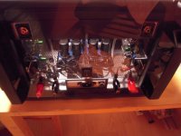
Alpeh J
Just finished this last night. Relatively easy, straightforward build came right up with no issues and holding steady 40ma after 12 hours burn in. No hum no hiss on 96db speakers, looks like it's going to be a keeper...
Just finished this last night. Relatively easy, straightforward build came right up with no issues and holding steady 40ma after 12 hours burn in. No hum no hiss on 96db speakers, looks like it's going to be a keeper...
Attachments
@Carlp, most Pass amps use CL60s (2 for 110V and 1 for 240V).
They're put on the primary side because with large transformers there's a lot of inrush just to create the magnetic field -- never mind the cap bank after it.
Thank you Jeff!
My travails with CL60s in a Pass Amp "M2" on USA (115VAC) mains, are listed here. My M2 amplifier kept popping its 2.5A slow-blow fuse in the primary, every couple dozen "inrush" events. So I built some test equipment and I investigated for myself.
Readers may wish to zoom in upon message #13 of that thread, in which Nelson Pass remarks
Allow me to repeat Nelson Pass's remark: "And not actually a CL-60".
This does not mean you will automatically get lousy results with a CL-60. It only means that First Watt customers got (presumably excellent) results with a NOT CL-60. Food for thought.
Readers may wish to zoom in upon message #13 of that thread, in which Nelson Pass remarks
[The first Watt M2 uses two inrush current limiting thermistors for USA mains]
And not actually a CL-60.
Allow me to repeat Nelson Pass's remark: "And not actually a CL-60".
This does not mean you will automatically get lousy results with a CL-60. It only means that First Watt customers got (presumably excellent) results with a NOT CL-60. Food for thought.
Member
Joined 2009
Paid Member
There exists many different NTC's. Instead of a 10 ohm maybe a 22 ohm will be better for 240 VAC......like this one:
B57237S0220M000 | EPCOS Termistor, 22Ω +-20% Tolerance, 3100mW, For Blod motorstart, switch-mode stromforsyning, 90s, 15 (Dia.) x 7mm | RS Components
B57237S0220M000 | EPCOS Termistor, 22Ω +-20% Tolerance, 3100mW, For Blod motorstart, switch-mode stromforsyning, 90s, 15 (Dia.) x 7mm | RS Components
Have some of these 10 ohms. Will try them first. It is possible also to set two in series. Think it will work with either one or two of these in a serial connection.
B57364S0100M000 | EPCOS Termistor, 10Ω +-20% Tolerance, 5100mW, For Blod motorstart, switch-mode stromforsyning, 100s, 21 (Dia.) x 7mm | RS Components
Good to use what you have "on the shelf"!
B57364S0100M000 | EPCOS Termistor, 10Ω +-20% Tolerance, 5100mW, For Blod motorstart, switch-mode stromforsyning, 100s, 21 (Dia.) x 7mm | RS Components
Good to use what you have "on the shelf"!
I will build an universal PSU for Firstwatt power amps. For this I have ordered two 500 VAs where each has 2x18 V secondary. It will be external PSUs that can be reused (dual mono). The nice thing with DIY is that you can "overdo" things a bit. But these large transformers probably like to have a kind of softstart. Either a thermistor in primary or a dedicated circuit which makes a well defined delay with reduced current. The thermistor solution looks almost too simple.....does it really work? ….why do people built boards with 555 timers, relay, regulator etc. etc. when it can be made that simple using a thermistor in the primary?
I used a 1000 VA transformer in my BA3, like 6l6's BA3 build guide did, and used the Diystore soft start he used, works great! You might need two...
Russellc
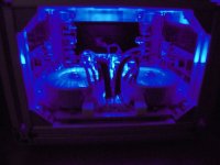
Cooking an M2X
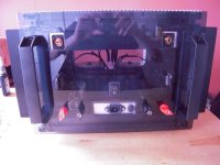
Hello sound-gourmets,
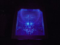
the hooby-cook made a nightshift yesterday. Made the backpanel of the M2X.
Acryl translucent dark grey.
Drilling, jigsaw, file, sandpapers, polishing,.....
I feel like this
Cheers
Dirk
Hello sound-gourmets,
the hooby-cook made a nightshift yesterday. Made the backpanel of the M2X.
Acryl translucent dark grey.
Drilling, jigsaw, file, sandpapers, polishing,.....
I feel like this
Cheers
Dirk
Attachments
answer to SOV
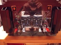
Hello Sov,
I couldn't compare the inputboards soundwise. Yesterday I made the backpanel
and added the missing resistor on the Norwood board (thanks to the eagle-eyes
of Mark Johnson). And I changed the Resistor R6 and the trimpot RV1 on the
mainboard to get more adjustability of the offset at the outputs.
I measured - 44mV and - 49mV offset which is for me to high. Although I played
music over the M2X.
Waiting for my frontpanel.
Then more listening tests.
But I think I should describe that in the M2X-thread? This is 'pictures of your diy Pass amplifier' - thread?
Greets
Dirk
- Home
- Amplifiers
- Pass Labs
- Pictures of your diy Pass amplifier