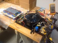
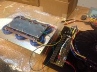
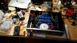
My upcoming Pass X amp monoblocks, a few pictures of the supply prototype. 1.5KVA Plitron LoNo power transformer, weight a ton (16Kg) but perfectly silent and as claimed by Plitron, the inrush current is really reduced.
Discrete dual bridge rectifiers (one per secondary) with chassis mounted heatsink, Softstart using a classic 555 timer to bypass a power resistor with a 30A relay, industrial power connectors. Classis style Pass caps bank with copper buss bar. It is a tough, powerful power horse of a power supply It won't crash on power demand while heavily biased in Class-A.
Discrete dual bridge rectifiers (one per secondary) with chassis mounted heatsink, Softstart using a classic 555 timer to bypass a power resistor with a 30A relay, industrial power connectors. Classis style Pass caps bank with copper buss bar. It is a tough, powerful power horse of a power supply
It won't crash on power demand while heavily biased in Class-A.Attachments

Last edited:
Zen
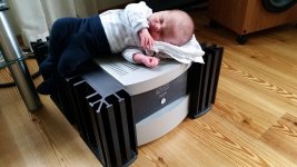
On the photo you can see a Zen with regulated PSU and SGS TO-3 mosfets.
I used the case of an old ML333.
Zen sounds better anyway. (of course this is like comparing a bulldozer with an oscilloscope)
My daughter (middle name Elna) is enjoying the gentle heat of single ended class A
Actually I sent this photo to Elna in Japan too.
No reply yet so I am thinking if we should have named her Nichicon or Epcos instead
I can take inside photos later, but it is not nice and tidy inside yet.
I would need to find a toggle on/off relay board from somewhere.
I do not really make PCBs myself anymore.
With such a board, I could utilize the momentary switch on the front of the ML case.
Even better if it had soft start built in.
Attachments
......
My daughter (middle name Elna) is enjoying ........
simply adorable ..........
On the photo you can see a Zen with regulated PSU and SGS TO-3 mosfets.
Which Zen?
Get me off here. My leg is burning..................my daughter ............ is enjoying the gentle heat of single ended class A ................
My daughter (middle name Elna) is enjoying the gentle heat of single ended class A
jlithen:
I'm with ZM on this -- the photo is really touching. Congratulations on both the amp and Elna (or "Panasonic"?).
Regards,
Scott
My upcoming Pass X amp monoblocks, a few pictures of the supply prototype. 1.5KVA Plitron LoNo power transformer, weight a ton (16Kg) but perfectly silent and as claimed by Plitron, the inrush current is really reduced.
Discrete dual bridge rectifiers (one per secondary) with chassis mounted heatsink, Softstart using a classic 555 timer to bypass a power resistor with a 30A relay, industrial power connectors. Classis style Pass caps bank with copper buss bar. It is a tough, powerful power horse of a power supply
Algar,
did you take the transformer out of the potted enclosure? I use LoNo by Plitron and they are simply the best to me...they come with that nice potted enclosure. Did you have it custom made for you or you bought it second hand?
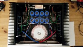
Custon made, and no potted enclosure. With the caps bank mounted over the transfo, the potted case didn't fit in my chassis. Plitron used a core with lower height, but larger diameter (same VA) so it would fit.
They made it custom (qty: 2), with the dual primaries at 120V, not 115 or 117V, and the secondaries voltage that I wanted. Price was also lower without the enclosure, and not that bad all thing considered for such custom made. high power, high quality transfo. Also I was quite impressed that at startup, with no charge in the caps, that there is not a very large power surge.
Usually with a 1KVA transfo, we can hear the sound of the current surge, lights in the room may flick shortly, etc. But with this 1.5KVA LoNo, nothing, quite impressive.
I used 2x 14.7ohms 20W chassis mounted Dale/Vishay resistors in parallel bypassed with a 30A relay as softstart. The resistors stay cold to the touch. Very good...
On the photo you can see a Zen with regulated PSU and SGS TO-3 mosfets.
I used the case of an old ML333.
Zen sounds better anyway. (of course this is like comparing a bulldozer with an oscilloscope)
My daughter (middle name Elna) is enjoying the gentle heat of single ended class A
Actually I sent this photo to Elna in Japan too.
No reply yet so I am thinking if we should have named her Nichicon or Epcos instead
I can take inside photos later, but it is not nice and tidy inside yet.
I would need to find a toggle on/off relay board from somewhere.
I do not really make PCBs myself anymore.
With such a board, I could utilize the momentary switch on the front of the ML case.
Even better if it had soft start built in.
Love this picture, showed it to all my family....
Custon made, and no potted enclosure. With the caps bank mounted over the transfo, the potted case didn't fit in my chassis. Plitron used a core with lower height, but larger diameter (same VA) so it would fit.
They made it custom (qty: 2), with the dual primaries at 120V, not 115 or 117V, and the secondaries voltage that I wanted. Price was also lower without the enclosure, and not that bad all thing considered for such custom made. high power, high quality transfo. Also I was quite impressed that at startup, with no charge in the caps, that there is not a very large power surge.
Usually with a 1KVA transfo, we can hear the sound of the current surge, lights in the room may flick shortly, etc. But with this 1.5KVA LoNo, nothing, quite impressive.
I used 2x 14.7ohms 20W chassis mounted Dale/Vishay resistors in parallel bypassed with a 30A relay as softstart. The resistors stay cold to the touch. Very good...
Hi,
what is the secondary voltage on that Plitron transfo. ? How many output-fets are you planning to use?
I'm not familiar with operating on 110/120Vac supplies but extrapolating from my 240Vac experience, you could use a T12A fuse.....................Usually with a 1KVA transfo, we can hear the sound of the current surge, lights in the room may flick shortly, etc. But with this 1.5KVA LoNo, nothing, quite impressive.
I used 2x 14.7ohms 20W chassis mounted Dale/Vishay resistors in parallel bypassed with a 30A relay as softstart. The resistors stay cold to the touch. Very good...
That should not blow in starting, when passing a maximum current of 25Aac.
You would need 3 parallel 14r7 resistors to give an added starting resistance of 4r9.
What fuse did you use for your 1500VA 120Vac transformer?
Thanks for all the comments guys!
It is Zen 4, FETs are P571? I think.
Highish gate capacitance, but otherwise good specs.
I get really low dist for a single ended amp and the input buffer FET takes care of the capacitance issue reasonably well as response is quite flat up to 70/80kHz.
It is Zen 4, FETs are P571? I think.
Highish gate capacitance, but otherwise good specs.
I get really low dist for a single ended amp and the input buffer FET takes care of the capacitance issue reasonably well as response is quite flat up to 70/80kHz.
Algar,Custon made, and no potted enclosure. With the caps bank mounted over the transfo, the potted case didn't fit in my chassis. Plitron used a core with lower height, but larger diameter (same VA) so it would fit.
They made it custom (qty: 2), with the dual primaries at 120V, not 115 or 117V, and the secondaries voltage that I wanted. Price was also lower without the enclosure, and not that bad all thing considered for such custom made. high power, high quality transfo. Also I was quite impressed that at startup, with no charge in the caps, that there is not a very large power surge.
Usually with a 1KVA transfo, we can hear the sound of the current surge, lights in the room may flick shortly, etc. But with this 1.5KVA LoNo, nothing, quite impressive.
I used 2x 14.7ohms 20W chassis mounted Dale/Vishay resistors in parallel bypassed with a 30A relay as softstart. The resistors stay cold to the touch. Very good...
I have a custom 1.2KKW LONO Plitron with potting and enclosure. There is very little kickback to the mains but the most impressive thing is how quiet these transformers are. Very, very quiet operation compared to other transformers I had compared it with when building my first prototype.
Now I am stepping up for a new project and going to a custom 2KVA Lo-No potted on enclosure.
The sound of these transformers IMO is great, definitely the best I have tried! They are going to be much more expensive compared to other competitors, but I feel that quality is absolutely top notch. I personally can’t be more pleased with Plitron!!
I am wondering you are using a 1.5KVA transformer I am assuming one per channel since you have bought 2 units. What output power do you have and what is the amount of Class A you are injecting?
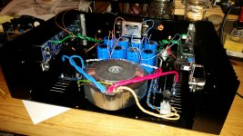
I finally got my F5 build finished today. It fired up nicely without blowing up. Biasing the output stage went well too, having it set at 650mV over the 0R50 resistors equals to 1.3A of current through each of the FETs. The output DC offset is within a few mV to zero. The heatsinks settled at 46°C after an hour of idling along, which is 21°C above ambient.
I looked a some waveforms through the scope, the output looks clean and free of hum or noise. Tomorrow I'll hook it up to some test speakers
I looked a some waveforms through the scope, the output looks clean and free of hum or noise. Tomorrow I'll hook it up to some test speakers
Attachments
I finally got my F5 build finished today. It fired up nicely without blowing up. Biasing the output stage went well too, having it set at 650mV over the 0R50 resistors equals to 1.3A of current through each of the FETs. The output DC offset is within a few mV to zero. The heatsinks settled at 46°C after an hour of idling along, which is 21°C above ambient.
I looked a some waveforms through the scope, the output looks clean and free of hum or noise. Tomorrow I'll hook it up to some test speakers
I have to admire your patience to wait till another day to hear how they sound.
- Home
- Amplifiers
- Pass Labs
- Pictures of your diy Pass amplifier