Very cool Captain. I like the heatsinks ")
Hi, many thanks to Mr Pass and the diyaudio community here
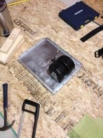
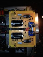
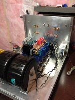
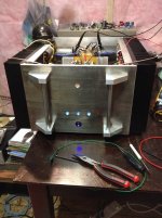
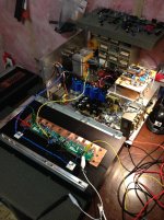
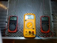
Here are some photos my little ACA build. It's still a bit rough around the edges, but if I wait to finish I'll never post photos. I have sandwiched the MOSFETs between a PC CPU heatsink and a small 40x40mm heatsink. The MOSFETs all sit nicely within the foot print of the heatsinks, with a few mm of space between them.
I used a Cooler Master PC CPU heatsink (this one), which I picked up dirt cheap on ebay (~£10GBP). It's quite nice because it has metal feet with holes, so I was able to screw it down through the box. I've tried some other CPU heatsinks, but this one has been the best so far.
I removed the big fan from the CPU heatsink, it happily radiates passively. The 40x40mm heatsink is using a small fan, as the black side of the MOSFETs does seem to get warm otherwise. The small fan is supplied through a small DCDC switch mode step down (ebay again, ~£3GBP), just visible as a blue PCB in one of the images. That small fan is running at 5v (rated for 12v), so it is not audible. As for signal noise... the amp runs from a switch mode supply anyway, but I'm not sure! I'm delighted with how the amp sounds in any case.
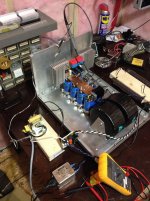
In use the PC CPU measures at 50*C max. Without the small fan active the that rises to 70*C. So it is possible to run it passively and hot
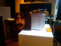
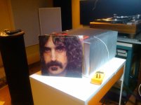
I'm driving a pair of Fostex 206EN in transmission line enclosures. I've been using this amp for 5 months now
Thanks again!
F5 Turbo V2
Hello,
Here are some of the pics from my F5 Adventure. Many thanks to all who have helped along the way! Infinite thanks to Nelson for sharing his ideas and schematics in such a clear and concise manner.
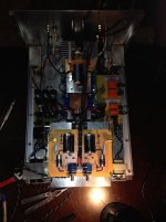
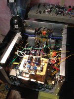
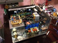
This was my first amp. In hindsight I should have started smaller than a F5 V2. I integrated a B1 preamp into it as well. It's probably not a clean as it could be in terms of wiring but it measures well and is very quiet. I'm bringing it in to work and chucking it on the spectrum analyzer to see what kind of distortion specs I get. Biased up to nearly 3 amps per channel. Sinks get to 49 degrees.
Cheers!
Hello,
Here are some of the pics from my F5 Adventure. Many thanks to all who have helped along the way! Infinite thanks to Nelson for sharing his ideas and schematics in such a clear and concise manner.
This was my first amp. In hindsight I should have started smaller than a F5 V2. I integrated a B1 preamp into it as well. It's probably not a clean as it could be in terms of wiring but it measures well and is very quiet. I'm bringing it in to work and chucking it on the spectrum analyzer to see what kind of distortion specs I get. Biased up to nearly 3 amps per channel. Sinks get to 49 degrees.
Cheers!
Attachments
F5 Turbo V2
Hello,
Here are some of the pics from my F5 Adventure. Many thanks to all who have helped along the way! Infinite thanks to Nelson for sharing his ideas and schematics in such a clear and concise manner.
This was my first amp. In hindsight I should have started smaller than a F5 V2. I integrated a B1 preamp into it as well. It's probably not a clean as it could be in terms of wiring but it measures well and is very quiet. I'm bringing it in to work and chucking it on the spectrum analyzer to see what kind of distortion specs I get. Biased up to nearly 3 amps per channel. Sinks get to 49 degrees.
Cheers!
F5 Turbo V2 Continued
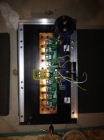
The last few pics from my F5 V2 build!
Cheers.
The last few pics from my F5 V2 build!
Cheers.
Attachments
Mounting bolts
Ah, why yes. After many years of lurking on this forum I was sure at some point I would be having a conversation with you Andrew! Good to finally make you acquaintance.
It's actually 2 seperate bolts. Counter sunk heads into the epoxy potting of the donut and the chucked a 5 mil layer of kapton between them with some high voltage putty to help with any vibration or shifting.
Cheers
I have been told not to write in a post Thread but I can't ignore what I see in post2902, transformer mounting bolt.
How is/are the bolt/s done up?
Ah, why yes. After many years of lurking on this forum I was sure at some point I would be having a conversation with you Andrew! Good to finally make you acquaintance.
It's actually 2 seperate bolts. Counter sunk heads into the epoxy potting of the donut and the chucked a 5 mil layer of kapton between them with some high voltage putty to help with any vibration or shifting.
Cheers
My F3 Clone. From Serbia made by Impuls
An externally hosted image should be here but it was not working when we last tested it.
An externally hosted image should be here but it was not working when we last tested it.
An externally hosted image should be here but it was not working when we last tested it.
An externally hosted image should be here but it was not working when we last tested it.
An externally hosted image should be here but it was not working when we last tested it.
An externally hosted image should be here but it was not working when we last tested it.
An externally hosted image should be here but it was not working when we last tested it.
An externally hosted image should be here but it was not working when we last tested it.
An externally hosted image should be here but it was not working when we last tested it.
An externally hosted image should be here but it was not working when we last tested it.
Ah, why yes. After many years of lurking on this forum I was sure at some point I would be having a conversation with you Andrew! Good to finally make you acquaintance.
It's actually 2 seperate bolts. Counter sunk heads into the epoxy potting of the donut and the chucked a 5 mil layer of kapton between them with some high voltage putty to help with any vibration or shifting.
Cheers
If this is your first amp , you can be proud! Nice build.
Wow nmiro really nice! I see some influence of Zen Mod
The coins and very thin input signal wiring
Thanks, but all credit goes to Impuls. There are some uncertainties regarding copyright of coins. One thing is certain: the inflationary money has a positive effect on the sound
Eggplant,
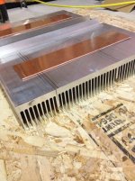
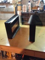
What a nice monster! How do you screw the alu plate to the square bar? Dis you drill holes all the way and fix the screw with nuts&bolts? Or did you tap the hole? Heatsink tapped, or with nuts&holes (drill all the way)?
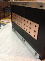
Thanks! I drilled all of the holes to a depth just shy of all the way through and then used M5 M4 or M3 bottoming taps. There is not a single hole directly through the heatsinks.
Cheers.
Uh okay. One last question. Did you (black) anodized the heatsinks by yourself? How did you do that? Any links? Thx Eggplant!Thanks! I drilled all of the holes to a depth just shy of all the way through and then used M5 M4 or M3 bottoming taps. There is not a single hole directly through the heatsinks.
Cheers.
Uh okay. One last question. Did you (black) anodized the heatsinks by yourself? How did you do that? Any links? Thx Eggplant!
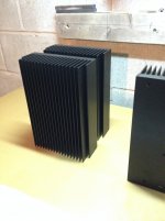
No problem. Glad to help. I actually purchased a 6 foot length of extrusion, chopped it up an then got the whole works anodized. It was 125$ for the whole works and I have enough to do up a couple of F5s. I'm building a set of full range single driver speakers next and I think I'm going to build the f5 monoblocks into the enclosures.
Cheers
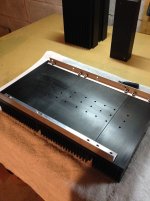
Here is my latest. Just in the process of biasing, and the faceplate needs to be straightened out, but that's just adjusting some screws..... the bias still wanders a little, and I think the noise I complained about now, is probably sloppy wiring.
Will show guts soon. The heatsinks are 2 pieces 10"x10" each side. There are 4 pairs per channel, and it's doing about 90 watts with 50 deg heatsinks.
Will show guts soon. The heatsinks are 2 pieces 10"x10" each side. There are 4 pairs per channel, and it's doing about 90 watts with 50 deg heatsinks.
Attachments
Last edited:
- Home
- Amplifiers
- Pass Labs
- Pictures of your diy Pass amplifier