
Hi culture,
Nice metalwork.
2 questions;
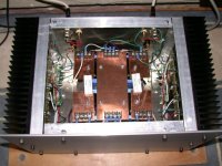
How big are your heatsinks.....(they look to be same as the ones i got for my F3 ( 295mm x 150mm x 80mm)) ?
How hot do they get on prolongued listening ?
...just checking if mine will take the F3's heat
Hi CeeVee
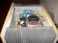
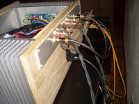
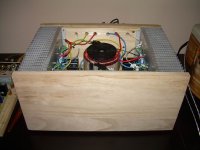
Thanks for the compliment, it a true kitchen table effort, drilling and all
The heatsinks are 16x23x7,5 cm. I don't know the actual temperatures. I can touch them for more than five seconds, hot but no problem and i have to confess the amp is not in the most well ventilated place.
cheers,
c.
Aren't there also arguments for not using an unlimited number of caps? In chip amps, which require less power smoothing, it is quite common to use as little as 4,000uF per channel, the argument being that it increases the audible speed (immediacy) of the amp without losing bass. Obviously that is a different situation, but isn't there an argument to say that too much capacitance might slow a Class A amp down?
As I said before "The ear will decide".
When I have done the listening tests I will let everyone know what my impressions are.
My F2.
An externally hosted image should be here but it was not working when we last tested it.
I've never heard of a Class A amplifier sufferring from too much PSU supply capacitance. It is true that the ESR of the caps should be kept low so that the impedance of the PSU is low.
Some of the more bizzarre Hiranga Class A amplifiers even go the extreme of using car batteries in place of the capacitors.
Surely the aim is to get a PSU that provides a rock stable voltage at full power whilst also having a low impedance. ie massive Transformer and even bigger PSU caps.
I'm using 3 x Dubillier 33000uF / 75V Computer Grade caps per rail - 4 rails in total for the two amps. These caps actually measured at nearly 100000uF each when I was selecting them.
The sound was absolutely stunning, however, I'm now looking for a better pair of speakers as the amp has shown up the weaknesses of my B&W DM602s3's.
Andy, your amp in picture looks real nice
yet, a small note about transistor mount
transistors should ideally be mounted around middle of heatsink, or even better right below, vertically
to me it appears like you have them very close to top of heatsink
You may well be right. This was my first attempt at a Class A design. I solved the problem by reducing the quiescent current slightly and replacing the silpads with mica washers.
NEVER again will I use SILPADS, they are ABSOLUTELY USELESS at high power.
hey, we need more amp pictures
Here's my A30 built in 2003.
Attachments
My diy F5
Hi,
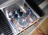
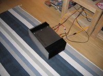
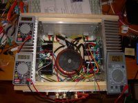
this is my f5 finished at the end of June.
Built around cviller ampli and supply board in a dual mono config.
Sounds very smooth with a special bottom end energy in my system.
Dc at output is always under 2,5 mV with a bias around 0,6 volt.
Thanks to Mr. Pass, Cviller and to all f5 builders
Hi,
this is my f5 finished at the end of June.
Built around cviller ampli and supply board in a dual mono config.
Sounds very smooth with a special bottom end energy in my system.
Dc at output is always under 2,5 mV with a bias around 0,6 volt.
Thanks to Mr. Pass, Cviller and to all f5 builders
Attachments
Hi,
this is my f5 finished at the end of June........
naah ..... give us more pics and than I'll say Fugly!

I like wood
make some decent holes in bottom , same on top plate ..... soak these wood plates with some decent oil , and I would say Fugly!

yeah I will do it.
When a new ampli starts to sound I always think building a new one instead of finishing it
Anto
- Home
- Amplifiers
- Pass Labs
- Pictures of your diy Pass amplifier