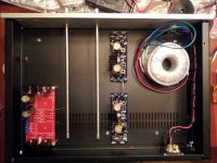
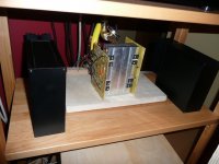
Is a dual mono V2 with 2 PSU and 2 Trasformers 600VA. Here some pictures during the building. I hope you enjoy the pictures as I enjoy the sound
I build my F5T V2 being re-located in Korea.... what not easy but here is the result
This is Super Like...

F5 from Poland
I can only add that the construction took more than a year, all matched transistors and resistors, capacitors have not found such as the original so I used the Nippon Chemi-Con 33000uf, 400VA transformer.
I built a B-1, but did not give all the power of F5, so I decided to JC-2 from ebay.
Now I do not know how to build a model ...
Enrico, did you build a regular F5 before you made this one. If you did, can you describe the difference in sound between the two?
Your build is top shelf.
Thanks Bob
About the F5 I don' t build it, so I can't compare the two
Ciao
Enrico
Is a dual mono V2 with 2 PSU and 2 Trasformers 600VA. Here some pictures during the building. I hope you enjoy the pictures as I enjoy the sound
Wow emyeuoi, very, very nice build
your wiring and positioning is so well thought ...
Love the frontpanel
Enjoy the sound, Walter

.........I built a B-1, but did not give all the power of F5, so I decided to JC-2 from ebay....
That's the exact combo I have been using for the past fer weeks. Coming directly off the DAC, with all audio drivers on my PC (JRiver Media Studio with flac files) turned off, the F5 is just under what I like for some selections. The JC-2 provides more than enough gain and at high quality. I've been advised that the 02 headphone amp/pre is another great alternative that passes a super clean signal to the Pass offerings - plan to try one in the near future.
The other obvious alternative for getting just a bit more SPL from the F5 builds is a set of speakers with higher efficiency than the Sunflowers I'm using now. This may not be the appropriate thread, but I've been thinking about asking the members of the F5 community for recommendations for a DIY speaker that helps the amps sound just a little bigger. It's my understanding the highly regarded B-1 would then be able to do it's magic and retain the KISS approach NP has at the base of his designs.
I hadn't planned on doing much more speaker building, but the ACA, F5 and BA-3 experiences I've had this past year could push me back into the wood-shop for a shot at better match for these amps.
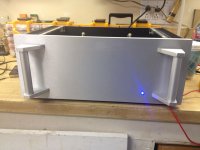
Here is the final pic of my F5 before I button it up and move to the listening room. DIY boards, 4U case, handles. Added hole for blue LED power light.
Bias holds steady after playing all day. Heat sink is about 22degC above ambient, all and all a beautiful and stable design. Thanks Nelson and fellow diy'ers.
Bias holds steady after playing all day. Heat sink is about 22degC above ambient, all and all a beautiful and stable design. Thanks Nelson and fellow diy'ers.
Attachments
Wow Walter,
you have no idea how much your works has inspired my creation. I decided to make the F5T V2 after seeing the beautiful pictures of your V3.
Your words make me really pleased.
Thanks and Regards,
Enrico
Here is the final pic of my F5 before I button it up and move to the listening room. DIY boards, 4U case, handles. Added hole for blue LED power light.
Bias holds steady after playing all day. Heat sink is about 22degC above ambient, all and all a beautiful and stable design. Thanks Nelson and fellow diy'ers.
Looks very nice ! Any pics of the inside?
Walter
Here is the final pic of my F5 before I button it up and move to the listening room. DIY boards, 4U case, handles. Added hole for blue LED power light.
Bias holds steady after playing all day. Heat sink is about 22degC above ambient, all and all a beautiful and stable design. Thanks Nelson and fellow diy'ers.
Is it the finish you have on it or how the heck did you manage to keep the front so mar free?
That is an awesome build and nice handles to match.
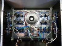
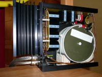
Here is the guts of the amp. Taken before handles and front LED added. Also, I had not twisted AC wiring yet. All nice and neat now. Note stable bias! Great design Nelson.
Small pcb at the bottom left is for speaker protection. Cheap eBay product. I have not hooked it up yet.
Small pcb at the bottom left is for speaker protection. Cheap eBay product. I have not hooked it up yet.
Attachments
Last edited:
Is it the finish you have on it or how the heck did you manage to keep the front so mar free?
That is an awesome build and nice handles to match.
Thanks. Two tips on the case
1. Assemble sides and front, then back, bottom and top. DO NOT fully tighten screws until everything but the top is together. Tighten front screws first. Then, everything fits.
2. Keep shipping plastic on all parts right until they are installed. For front panel, I cut a piece of cardboard and attached to surface with painter's tape. After I installed the front panel, the cardboard and tape came off. It is REALLY easy to scratch the soft aluminum.
Regarding the handles, I would recommend using a drill press with new and sharp bits to drill through the holes for the handles. You will also need to very slightly taper the holes from the front just a fraction to break the 'lip' created when the hole was drilled through. The handles may not mount flat if you do not. You may be able to do this whole operation by hand, but I didn't want to.
The handle cylinders were a bit short, and rattle around. I used a sliver of cork in the bottom handle holes to stop the rattling. Check that the included screws actually fit in the countersink holes on the back of the front panel. Two of the eight included in my handle set were too big. Could not fit in completely. I enlarged the countersink slightly, but again, not something that I would have attempted without a stable drill press and very sharp bits.
I really enjoy your pics. Really!
I'm just about to build the F5T v.2 in a similar setup like you. Same pcbs for PSU and AMP with a dual mono setup. (2x800VA trafos)
May I ask you how bias the amp? And how did you set P3?
Thanks and Regards,
Kai
I'm just about to build the F5T v.2 in a similar setup like you. Same pcbs for PSU and AMP with a dual mono setup. (2x800VA trafos)
May I ask you how bias the amp? And how did you set P3?
Thanks and Regards,
Kai
Is a dual mono V2 with 2 PSU and 2 Trasformers 600VA. Here some pictures during the building. I hope you enjoy the pictures as I enjoy the sound
Hi Mallard,
Is a pleasure to know that after just "taking" information and help from this fantastic forum I can also contribute (maybe just a little) to help other DYIers.
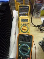
Actually the bias is 360 mV. After various replies from Buzzforb and AndrewT they suggest to bias the amply very very slow and go to max 380/400 mV. In my understandingscratch the risk is that if the diodes in parallel to the FET start to conduct during the bias set-up, the bias become unstable and can run away destroing the FETs.
The P3... as suggested in the FW F5 Turbo article the P3 was set at the middle of his value before to sold them. I have no idea how can set him with only a DMM but anyway the ampli is sounding so amazing that I don't fill I need to touch it.
Enjoy your build
Enrico
Is a pleasure to know that after just "taking" information and help from this fantastic forum I can also contribute (maybe just a little) to help other DYIers.
Actually the bias is 360 mV. After various replies from Buzzforb and AndrewT they suggest to bias the amply very very slow and go to max 380/400 mV. In my understanding
scratch the risk is that if the diodes in parallel to the FET start to conduct during the bias set-up, the bias become unstable and can run away destroing the FETs.The P3... as suggested in the FW F5 Turbo article the P3 was set at the middle of his value before to sold them. I have no idea how can set him with only a DMM but anyway the ampli is sounding so amazing that I don't fill I need to touch it.
Enjoy your build
Enrico
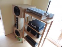
Liquid cooled Alpeh-X
I have built this about 6 years ago according Grey Rollins schematic, and it´s still in use:
The coolant circulates only by gravity. (without a pump)
I have built this about 6 years ago according Grey Rollins schematic, and it´s still in use:
The coolant circulates only by gravity. (without a pump)
Attachments
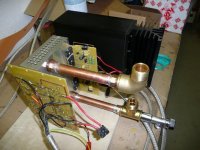
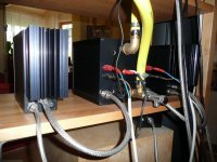
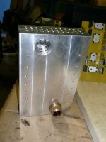
Very interesting James. Glad to see another member's approach to alternate cooling. Is the gauge for temp, flow or pressure? What's the function of the tall copper tube on top? I assume it's a fill port but it appears more sophisticated.
I think you are saying you believe not having a fan and/or pump is an advantage. I am using both to simply reduce the mass of the entire system. Did you try smaller tube/hose and still maintain adequate coolant flow?
I think you are saying you believe not having a fan and/or pump is an advantage. I am using both to simply reduce the mass of the entire system. Did you try smaller tube/hose and still maintain adequate coolant flow?
- Home
- Amplifiers
- Pass Labs
- Pictures of your diy Pass amplifier