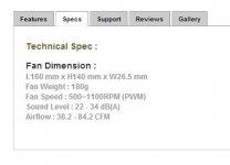
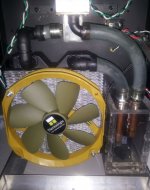
The fan is really not that much of a problem. It starts just fine with a straight connection from the 7.5 VDC wall wart. As shown in the specs it's designed to operate over a range of voltages. Asus motherboards have a feature called "Cool & Quiet" that will start the fan low and increase the speed as the system temps get higher. I'm not sure how sophisticated that technology on the MB is.
The pump also lists a range from 5 to 12 volts, but 7.5 with the pot turned all the way up is necessary to get it rolling. The only problem with that is slower pump speed = more heat removal.
DC 12V 6W PUMP MOTOR (may need to open in new tab/window)
I spoke to a friend yesterday who said low voltage AC starts can function as long as the amps are full and stable. As Andrew said in his email, some form of pulse circuit is necessary to pull off the same trick with DC. (Man-that's another gold star for Mr.T )
)
I think this unit might be what's needed and is tiny compared to those found at Home Depot and the like.
DC Motor Speed Control Switch
What do you think?
EDIT: evanc, if that works it would be even sweeter !
The pump also lists a range from 5 to 12 volts, but 7.5 with the pot turned all the way up is necessary to get it rolling. The only problem with that is slower pump speed = more heat removal.
DC 12V 6W PUMP MOTOR (may need to open in new tab/window)
I spoke to a friend yesterday who said low voltage AC starts can function as long as the amps are full and stable. As Andrew said in his email, some form of pulse circuit is necessary to pull off the same trick with DC. (Man-that's another gold star for Mr.T
)I think this unit might be what's needed and is tiny compared to those found at Home Depot and the like.
DC Motor Speed Control Switch
What do you think?
EDIT: evanc, if that works it would be even sweeter !
Attachments
Last edited:
I'm looking for some creative input here and I think this might be the best place to post this since it will end up being my own F5 amp picture one day. I'll be building an F5 using the diyAudio chassis and I've been trying to come up with something interesting to do with the blank front panel. The idea that I have is sort of like how schematics used to be printed on the inside casing of radio equipment. I took the F5 schematic and removed the nomenclature etc. leaving just the circuit symbols. The F5 circuit is just simple enough to where this might not look too busy. It would be engraved on the front with the engraving painted black. Any thoughts for improvement? If something like this has been done before either with a DIY Pass amp or something else, then I'd like to see how it turned out.
Attachments
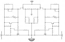
Any thoughts for improvement? If something like this has been done before either with a DIY Pass amp or something else, then I'd like to see how it turned out.
Sure would make it easy to troubleshoot the amp..... I mean, you'd have your primary documentation right on your front panel....(!)
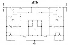
The only thing I would change is to flip the schematic so the output is on top.
Nice, that does make it look better.
Attachments
")
Nah, it would be on the front face of the unit. The intent is to make a faithful visual representation of the circuit but smooth some of the edges with some abstraction.
Not if I can't make them multicolored and blink.
AudioSan said:engrave it on a piece of plexi. and light it up with LED's
Not if I can't make them multicolored and blink.
Last edited:
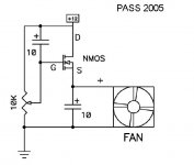
A simple circuit that tracks fan speed to water temperature shouldn't be very complicated. As water temperature goes up so it does fan speed.Asus motherboards have a feature called "Cool & Quiet" that will start the fan low and increase the speed as the system temps get higher. I'm not sure how sophisticated that technology on the MB is.
Thermo-Fan to keep your amplifier cool
"The temperature is set with VR1. Operate the amp until the normal temperature is reached, then adjust VR1 until the fan starts. Then back off very slowly until the fan stops again. Any increase over the normal temperature will start the fan, and promptly bring the temperature back down again."
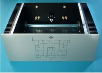
Here's my attempt to visualize my idea. I dunno, there's something missing. Maybe it would look better with handles.
It is a nice idea and it will probably work, but try this as an alternative (maybe you can mock it up like you did with the one you pictured): place the diagram/etching on the top cover/plate.
I have seen diagrams/info/scripting done on various amplifiers before, kind of like the wiring instructions you find on the top of a McIntosh MC205 (SS) cover or the MC275 (tube) transformers.
I don't think you should flip the diagram on its side, nor use the concentric arcs at input and output (see the sine wave NP uses to indicate larger signal), nor use some non-standard potentiometer-looking connection (with the arrow) to the V rails. Keep it as standard as possible...
- Home
- Amplifiers
- Pass Labs
- Pictures of your diy Pass amplifier