Hello to all of you!
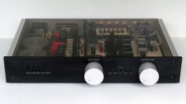
My name is Martin and this is my first post on this forum. I want to introduce myself with a finished project. It is another Balanced Zen Line Stage. A written report with more details will later be on www.PassDIY.com. For now I like to post some pictures of my version and a link to my web album.
Cheers, Martin
Attachments


Thank you all for looking and your kind words!
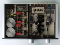
@PH 104: Yes, and that was the easy part for me. I am an engraver and work as an instructor in the arts and crafts department of a school. Thus I have access to a CNC-milling machine, software, lathe etc. We also have a department for electronics engineering and I could have made the circuit boards there, using industrial technology like a laser plotter and etching machine. To the great surprise of some colleagues of that department, I have it done on my own. I used available machinery and needed only an absolute minimum of advice which makes me proud.
@max426: Thanks for explaining “fugly”. And to give you an idea of the my working pace, Jim...
I have discovered the PassDIY web site during the winter holidays. In January I was reading and thinking about the project. The first parts arrived by the end of January and that was the time when I took up CAD drawing. The main board was milled March 8th, the first sound test was April 12th. That makes a total of just 10 weeks for building. I was very consequent and worked each day a bit and all the weekends. I guess that I have spent approx. 300 hours or so. Now you might think that teachers seem to be under occupied…. my timetable consists of 31 hours of instruction per week.
Member
Joined 2009
Paid Member
Thank you all for looking and your kind words!
... Now you might think that teachers seem to be under occupied…. my timetable consists of 31 hours of instruction per week.
Your project was your hands-on example in class, didn't you?
") ...that would be +31 hrs/wk!
...that would be +31 hrs/wk!Seriously, that hardware looks really great!

Grüß Gott, Martin.
I was extremely impressed by your workmanship, here.
I am working on a project myself which will require a certain level of good look, for the reason of WAF.
1) For the fine letters, especially under the LEDs in the input section on the front, how would be the best way of applying those? Screen print or engraving? What would be the easiest to have done for a person not himself capable of either?
2) Errr... how do you select the input? I see two knobs for input/output level (connected to pots on the inside) but no manual source selector. Something has got to control those small signal relays.
3) Is that a motor drive I see behind the output level pot? Are you planning some sort of remote control? (which would explain #2)
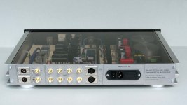
4) Also, how did you implement the source switching? It seems (from the number of relays) that you are switching the signal only and all audio grounds (incl XLR/RCA/cinch) are wired together constantly?
5) Are you happy with the sound of it?
Best regards,
Lars
I was extremely impressed by your workmanship, here.
I am working on a project myself which will require a certain level of good look, for the reason of WAF.
1) For the fine letters, especially under the LEDs in the input section on the front, how would be the best way of applying those? Screen print or engraving? What would be the easiest to have done for a person not himself capable of either?
2) Errr... how do you select the input? I see two knobs for input/output level (connected to pots on the inside) but no manual source selector. Something has got to control those small signal relays.
3) Is that a motor drive I see behind the output level pot? Are you planning some sort of remote control? (which would explain #2)
4) Also, how did you implement the source switching? It seems (from the number of relays) that you are switching the signal only and all audio grounds (incl XLR/RCA/cinch) are wired together constantly?
5) Are you happy with the sound of it?
Best regards,
Lars
Hello Lars,
Thanks for your kind comments. And please explain what “WAF” is…
1) Engraving certainly looks best. It is durable, clean and sharp when done well. I engraved the Pass logo 1, 5 mm deep and the fine lettering is just superficial at 0, 15 mm. If you have CorelDraw or some similar software you can create your own lettering and logo design. Draw your front plate 1:1 and then convert the text/drawing to vector lines. Select hairline, no filling. Then export and safe as vector data like .ai .eps. .dxf or .plt. All engraving shops can import these data and then easily do the engraving for you. Laser engraving would be an option too, I guess.
2) 3) 4) Yes, for output level and input selector I use a RC5 remote control. I have used a µcontroller that drives the motorized pot and offers five output signals for switching the input relays. Only the signal is switched.
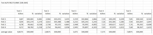
5) Maybe I now would go for an input selector board that is stuffed with resistor dividers for each input individually and leave out the input potentiometer -as I had planned at first. For the output I should have used a more precise and better potentiometer like the TDK CP 2500. I believe that the impreciseness of all these potentiometers can add up in a cumulative or compensating way. Sometimes I think I can hear volume level differences between both channels. I have measured one of these Alps and have found unexpected errors of +5, 4% - 4, 8% when set to 3 KOhm for example. If you compare 1/2 or 3/4 values are a bit better. Please see the spreadsheet below. CMR also would benefit greatly from a more precise attenuation.
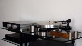
I use the balanced outputs. With the sound I am quite satisfied, it truly is great and very clear. No noise.
Best Regards,
Martin
Thanks for your kind comments. And please explain what “WAF” is…
1) Engraving certainly looks best. It is durable, clean and sharp when done well. I engraved the Pass logo 1, 5 mm deep and the fine lettering is just superficial at 0, 15 mm. If you have CorelDraw or some similar software you can create your own lettering and logo design. Draw your front plate 1:1 and then convert the text/drawing to vector lines. Select hairline, no filling. Then export and safe as vector data like .ai .eps. .dxf or .plt. All engraving shops can import these data and then easily do the engraving for you. Laser engraving would be an option too, I guess.
2) 3) 4) Yes, for output level and input selector I use a RC5 remote control. I have used a µcontroller that drives the motorized pot and offers five output signals for switching the input relays. Only the signal is switched.
5) Maybe I now would go for an input selector board that is stuffed with resistor dividers for each input individually and leave out the input potentiometer -as I had planned at first. For the output I should have used a more precise and better potentiometer like the TDK CP 2500. I believe that the impreciseness of all these potentiometers can add up in a cumulative or compensating way. Sometimes I think I can hear volume level differences between both channels. I have measured one of these Alps and have found unexpected errors of +5, 4% - 4, 8% when set to 3 KOhm for example. If you compare 1/2 or 3/4 values are a bit better. Please see the spreadsheet below. CMR also would benefit greatly from a more precise attenuation.
I use the balanced outputs. With the sound I am quite satisfied, it truly is great and very clear. No noise.
Best Regards,
Martin
Attachments
Hi Martin,
WAF = Wife Acceptance Factor. Some of us have to deal with that...! No open baffles for me, I suppose
Thanks for the tips, I already found some engravers in my area, which I will approach.
A relay attenuator also crossed my mind. Peter Daniel has a nice review of attenuators here along with his take on how to build one: http://www.diyaudio.com/forums/chip-amps/73538-search-perfect-attenuator.html
Have fun.
Rgds,
Lars
WAF = Wife Acceptance Factor.
Some of us have to deal with that...! No open baffles for me, I suppose Thanks for the tips, I already found some engravers in my area, which I will approach.
A relay attenuator also crossed my mind. Peter Daniel has a nice review of attenuators here along with his take on how to build one: http://www.diyaudio.com/forums/chip-amps/73538-search-perfect-attenuator.html
Have fun.
Rgds,
Lars

Thank you all for the kind words! My new project is.... F5 monoblocs. I got hold of special shaped used heatsinks and did a unique layout around these, very compact. Today I obtained a huge ammount of super 70 µm FR4 epoxy material for the boards- for free- directly from the Panasonic factory where they are produced. An engineer showed us round and it was very interesting to see the maufacturing process in detail. Will show the finished amp on this forum...
Cheers, Martin
Cheers, Martin
- Status
- This old topic is closed. If you want to reopen this topic, contact a moderator using the "Report Post" button.
- Home
- Amplifiers
- Pass Labs
- Balanced Zen Line Stage