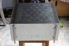
So, this my Quad ZV9!
I would like to present this apparatus, which I started preparing on 2006 summers yet, to you.
Although, maybe, I would have had a more important thing than this.
Now already anyway it doesn't matter.
That's it.
This worked already then, but I managed to reach away it recently with this in order for something to receive a form only.
Wacky Gyuri
http://public.bay.livefilestore.com/y1pRg-3XEe_iDxfNM4gmcBC_FwW5J_Y4LReO7GijJ_TN-0EJK7pGP6RtoJxt0F8MoGobkxOxO8y_AoovB4xMe2ZsA/ZV9_Front%20View.JPG
http://public.bay.livefilestore.com...yl0txmcq-t9B4yLUDeopX8I5M6w/ZV9_Back View.JPG
Attachments
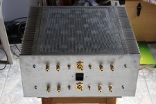

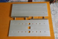
Holes
Yes, my dear. You know, his name is his flavour!
Because of that my dear Fotios my friend in a way more professional at me.
There are a little on its bottom otherwise.
But this only was a test drilling yet.
I produced very many slivers so whatever.
But I have to produce lunch again now.
Wacky Gyuri
Yes, my dear. You know, his name is his flavour!
Because of that my dear Fotios my friend in a way more professional at me.
There are a little on its bottom otherwise.
But this only was a test drilling yet.
I produced very many slivers so whatever.
But I have to produce lunch again now.
Wacky Gyuri
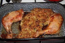
Well, this was the lunch, with some rice.:
http://ugoylw.bay.livefilestore.com/y1pRFXGAt_CS2TqLW1KPpV3hWYjYZl4A_6SK6sDfKRuRS5_GSrNZLJpJnsos7L69wWqhXpa3_53pD_6SjNxVCDTIDDSq0ARbplJ/S%C3%BClt%20csirkecomb%20t%C3%B6ltel%C3%A9kkel%20.JPG
http://ugoylw.bay.livefilestore.com/y1pRFXGAt_CS2TqLW1KPpV3hWYjYZl4A_6SK6sDfKRuRS5_GSrNZLJpJnsos7L69wWqhXpa3_53pD_6SjNxVCDTIDDSq0ARbplJ/S%C3%BClt%20csirkecomb%20t%C3%B6ltel%C3%A9kkel%20.JPG
Attachments
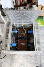
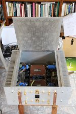
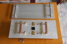
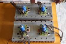
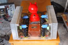
Inner view:
http://public.bay.livefilestore.com/y1pR1zC-Qw7TeD7vQNCDYJBb7sy9FyY8BZIuYcReAjNDwszQ6z91g5T2QZ7yAWP0EQMisVgo_-mXXGLfPJHI7tNwg/ZV9_Internal%20View1.JPG
http://public.bay.livefilestore.com/y1p6c-16nHtbrU7OTNfLQv6fM-49eCcoQcW7g3jsyqLj-zUnOrGwKG-0qA5k1J9Pa2m_F3U7X9C08HHnW8Ogwm3SQ/ZV9_Internal%20View2.JPG
Attachments
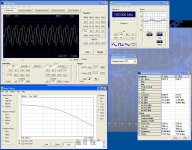
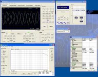
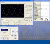
some measurement: (Thank you, Teuvo, and of course Pascal!)
CH1 divided by ten, CH2 is input.
Load approximately 8.9 ohms, resistive.
Let us not forget that it turn the phase with 180 degres.
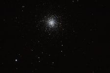
We imagine it meanwhile, what the sky may be like on the planet of a star in a globular cluster. Absolute
Wacky Gyuri
CH1 divided by ten, CH2 is input.
Load approximately 8.9 ohms, resistive.
Let us not forget that it turn the phase with 180 degres.
We imagine it meanwhile, what the sky may be like on the planet of a star in a globular cluster. Absolute
Wacky Gyuri
Attachments
Last edited:
Member
Joined 2009
Paid Member
Thank you, dear Bigun!
You know, I try to give it an uniform "family form" to my NP amplifiers.
Will be (it is concerned already) with a similar construction F4, with four pieces of amplifiers.
And it is good working since the approximately 10 years my Aleph.
http://www.diyaudio.com/forums/pass-labs/56454-my-good-old-new-aleph.html
You may see the "family members", each other on the next picture sitting in his neck:
http://public.bay.livefilestore.com...b0YOCorzuFt7E__w66B-H8qaD_eQ/My_A4_F4_ZV9.JPG
Wow massive. And neat too.
What active crossover, if I may ask?
Edit: No power switch?
massive. And neat too....
And because I wait for the active crossover very much.
...
What active crossover, if I may ask?
Edit: No power switch?
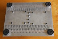
Some are additional pictures 1:
http://public.bay.livefilestore.com/y1phFYWv9uDOmz-bonBSH2Z1R1H3AOlakbBZcIddRhz7YDI-vuUiMADXECUo_UdVm_BZpgjGXtSpIMGnyV-hFHARQ/Back%20and%20front1.JPG
http://public.bay.livefilestore.com/y1pBrbdizluUPjlc2-EKeaYgAKy1VvSTYaSimz-sVCsFwbzdTTnvPgfGJB117M00guaBuHcXOmq_3OFy2swn9pg4A/Back%20and%20front2.JPG
http://public.bay.livefilestore.com/y1pPRNuZWcezKis93QOTc0xNYSCXz449BZ-Z2lT6rhatDY_vCt21033YosIaoPWgSQ0nKx9iOPvii1zzkCw6HJnCA/Bottom.JPG
Attachments
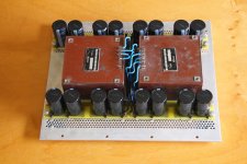
Some are additional pictures 2:
http://public.bay.livefilestore.com/y1pfgoQUvsZOjz_tDeAq9ZWlnttGyrzQ1eO6VLjGGNluajxViLnqrd9xFMjd6abouYnBUQTVBVwCXhFwEvPRnvQEw/Power%20supply.JPG
http://public.bay.livefilestore.com/y1pRl4ywdCYLfYpuvipxz0cDVzPm1iQzg8KOKld0Tzm7E4JDXa4-KYAqPKS0oh_xZoNnulptJGVOY1WNJJGq_rtbw/Amplifier%20moduls%20on%20heatsinks.JPG
http://public.bay.livefilestore.com/y1pxmC2EMp6kKsH5hbFccIzt6uMnmnaPKt7RuxRlE6wjjpoOTPeNx5-uWY2KZhXBu3WFndLO_aiE3n9y1tkkWjyqA/Without%20back%20top%20front.JPG
Attachments
Hi, Steve!
I do not grieve at it already more especially, how I shall connect it how from a temperature viewpoint the heatsinks.
I keep an eye on it because of that there are the fets evenly situated to the whole surface of the heatsinks.
In the brutal Aleph amplifier yet 5 mm aluminium sheet stripes screwed to the heatsinks. Three pieces per side, approximately 10 cm wide ones, with very many screws. Now already only with two 20x20 mm aluminium rod I clamp it together the pieces. The heatsink approximately a six metre long pieces produces. And the price of this a horror yes. Sure yet until all of them not so expensive, than Fishers, we say it. But the fins profile not so professional, and the surface is not handled.
Hi, Rodeodave!
31 kgs are his masses.
Original Papa kind B1 active crossover I wait for.
My granddad told me laughing it many times, if we went in that direction where they forgot to build a staircase upon a house. Then they realised that it is nowhere to go up onto the floors.
Huh, switch, I ask it, why?
I did not forget it actually, I did not have desire to take great pains over this. His front did not want to hurt.
Otherwise the switch is there on the extension cord.
Wacky Gyuri
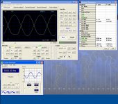
There is a little problem however here.
The from among four three channels alike. The fourth not so much good, than the others. Its amplification factor is somewhat smaller.
From a direct current viewpoint does not really differ from the others.
Which way let me be looking for the solution?
What can who built it already show with an oscilloscope?
How much does what I prepared match to the original one?
Attachments


Not so good channel:
Attachments


Hi, Rodeodave!
...
Original Papa kind B1 active crossover I wait for.
...
Wacky Gyuri
Me too.
About the troubled channel...can you post some pictures of the actual circuit? Maybe someone can spot a wrong resistor. Have you checked all the voltages?
So, this my Quad ZV9!
I would like to present this apparatus, which I started preparing on 2006 summers yet, to you.
Although, maybe, I would have had a more important thing than this.
Now already anyway it doesn't matter.
That's it.
This worked already then, but I managed to reach away it recently with this in order for something to receive a form only.
Wacky Gyuri
Looks fine, congratulations. Which schematic did you use, be very precise since I found different versions, mainly about the C5 issue. The best would be if you could scan / post it.
Thanks again.
Billy
http://public.bay.livefilestore.com...MoGobkxOxO8y_AoovB4xMe2ZsA/ZV9_Front View.JPG
http://public.bay.livefilestore.com...yl0txmcq-t9B4yLUDeopX8I5M6w/ZV9_Back View.JPG
- Status
- This old topic is closed. If you want to reopen this topic, contact a moderator using the "Report Post" button.
- Home
- Amplifiers
- Pass Labs
- So, this is my Quad ZV9!