Source Drain Gate
L Q1 3.77 13.77 8.15
R Q1 3.75 13.77 8.13
L Q2 3.78 13.82 8.15
R Q2 3.76 13.81 8.15
L Q3 21.85 13.82 17.30
R Q3 21.91 13.82 17.30
L Q4 21.84 13.91 17.20
R Q4 21.90 13.89 17.30
L Q7 .094 2.82 5.00
R Q7 .087 2.82 5.01
Voltage across R27-R30
L R27= .577, L R28= .577, L R29=.573, L R30=.576
R R27= .571, R R28= .572, R R29=.572, R R30=.570
The differential DC offset measured across the speaker terminals
Left 45mV (with load) 60mV (NO Load)
Right 25mV (with load) 35mV (NO Load)
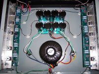
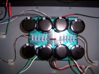
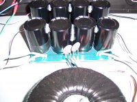
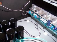
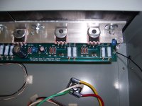
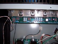
I've attached some pictures for reference , maybe you folks can see something I'm missing ...?
Thanks in advance for any help.
Regards, Daniel.
Attachments
I'm not sure that a good insight, but if the reverse polarity protection zener would be present.
Not on the board in relation to drawing, but the original wiring diagrams for comparison.
Maybe.
Gyuri
PS:
Of course, it would be better if the bottom could be seen.
Not on the board in relation to drawing, but the original wiring diagrams for comparison.
Maybe.
Gyuri
PS:
Of course, it would be better if the bottom could be seen.
Last edited:
Bad solderings could be a cause of your problem.
Apart from that, a signal tracer can be made with very simple tools.
If you have a signal generator, you can inject a 1kHz into the input and follow the signal path with your multimeter in AC mode.
Else, internet or a kind fellow member can provide you with a simple sine wave, playable from your PC.
I think it was not a bad idea, but I found this photograph, this is not the problem.
I'm sorry.
Perhaps there is someone better idea.
Papa Pass help us!
And besides, your name included in our daily prayers.
http://www.diyaudio.com/forums/group-buys/158838-f1-amplifier-psu-pcbs-free.html
Wacky Gyuri
PS:
And those diodes really zener diodes?
I'm sorry.
Perhaps there is someone better idea.
Papa Pass help us!
And besides, your name included in our daily prayers.
http://www.diyaudio.com/forums/group-buys/158838-f1-amplifier-psu-pcbs-free.html
Wacky Gyuri
PS:
And those diodes really zener diodes?
Last edited:
.... No scope unfortunately, just a Fluke 179 multimeter....
Regards, Daniel.
Does that Multimeter do AC volts. You can use that to trace the signal
I can bet that you feed it with unbalanced signal , and that you forgot to ground minus leg input
.
Hmmmm...
Gyuri, as chance would have it i did originally install the zeners backwards but the guys caught that in my other thread so they have been re-soldered correctly. Part is a 20v 1w 5% Diode Zener from Digi-key.
Zen Mod, I am indeed feeding unbalanced inputs but if you take a look at one of the pictures i posted you will see a small "red coated" copper jumper that i am using on the board to tie the ground and negative balanced input section on board together. (I think this is correct?) The input area of the board is mislabeled a bit but i was able to trace that before i started soldering.
flg, the multimeter does do AC volts. How would i use the multimeter to trace the signal. I'll measure the resistors you mentioned but what values would i be looking for ?
Netlist, can you expand a bit on your idea ? This is all a first for me so very little experience with electronics.
Tea Bag, just checked the speaker binding posts and no problems with grounding there.
Here's a very basic question. Can anyone verbally trace the grounding path for me ?
Thanks everybody, please keep the ideas coming.
Regards, Daniel.
Bingo !
Thank you Mr. Pass and flg for getting me to look more closely at the resistors. I started comparing the schematic from the owners manual for the f1 with the BOM posted somewhere here on DIY Audio, and the parts list that I ordered. The BOM has a mistake for R7-8 as it lists 392ohms instead of Kohms. Also I ordered R5-6 incorrectly as 562ohms instead of Kohms. Now I feel like the village idiot...did I mention that i hate de-soldering ?
I'll post an update when i get the correct values ordered and installed. Thanks again for the help.
Regards, Daniel.
Its Alive !!!
After a bit of desoldering and resoldering in the correct value resistors I now have a functioning F1. Paired with a DIY 24V Aikido and my C&C Abbys it sounds wonderful... huge bass and very revealing. Thanks to everyone for helping me get her up and running, and a big thank you to Mr. Pass for sharing.
Regards, Daniel.
Impedance
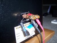
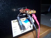
Thanks for the reminder NP. Been playing with it today and it definitely makes a difference. I did find after a little experimentation that the quality of the cap seemed important . Luckily i had a couple of unused Sonicaps laying around that just happened to be the right value. Does this look about right ?
Daniel
Attachments
- Status
- This old topic is closed. If you want to reopen this topic, contact a moderator using the "Report Post" button.
- Home
- Amplifiers
- Pass Labs
- Trouble Shooting an F1
