just a short note
I have two 2x 22V trafos for F5 projects
the +/-30V is about what the jfets can take
so I will test with the extern power supplies I had planned to build with those trafos
with the regs they will work for low power ClassA as well, be it Standard F5 or Juma's 2sk2013/2sj313 version")
now, should I go safe with the Renesas laterals first, as per schematic, or straight to the modification with the more exotic Toshibas
cheers
I have two 2x 22V trafos for F5 projects
the +/-30V is about what the jfets can take
so I will test with the extern power supplies I had planned to build with those trafos
with the regs they will work for low power ClassA as well, be it Standard F5 or Juma's 2sk2013/2sj313 version
now, should I go safe with the Renesas laterals first, as per schematic, or straight to the modification with the more exotic Toshibas
cheers
I personally would go with the Renesas parts first, because I am always interested in how component changes affect the sound. There are few opportunities for one person to make a comparison like this, same circuit, same power supply, different set of power devices.just a short note
I have two 2x 22V trafos for F5 projects
the +/-30V is about what the jfets can take
so I will test with the extern power supplies I had planned to build with those trafos
with the regs they will work for low power ClassA as well, be it Standard F5 or Juma's 2sk2013/2sj313 version
now, should I go safe with the Renesas laterals first, as per schematic, or straight to the modification with the more exotic Toshibas
cheers
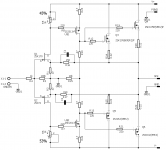
Terry, where did you see such a schematic (post#)?I am drawing this in Sprint6 and notice that the schematic says +24/+24. Is this an error? Is the lower rail -24?
Thanks, Terry
Excuse me.+25V/+25V. Post #1
I don't see that. Amp's upper rail is +25V (plus pole of V2) and the lower rail is -25V (minus pole of V3) with minus pole of V2 and plus pole of V3 connected to GND. Nothing unusual there...
Maybe you shouldn't rush into building this one before reading the whole thread, there are couple of things one needs to understand in order to build it properly.
Hi Juma,
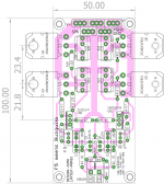
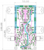
here is a layout that i did,
questions
1. is it ok to mount 2sj313 and 2sk2013 on main heat sink?
2. is the distance between o/p mosfets ok for proper dissipation?
3. can one use 0.33 ohm resistors for R14/15/20/22?
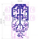
the second pic is for people who prefer high contrast.
all views from component side..
here is a layout that i did,
questions
1. is it ok to mount 2sj313 and 2sk2013 on main heat sink?
2. is the distance between o/p mosfets ok for proper dissipation?
3. can one use 0.33 ohm resistors for R14/15/20/22?
the second pic is for people who prefer high contrast.
all views from component side..
Attachments
Last edited:
1. Yes
2. No, except if you want to make a different amp out of it by biasing the output stage low. The layout in post #1 is better.
3. I would rather use 0R1 and select output mosfets from same batch to avoid current hogging
I would also change the biasing scheme to make it resistant to current changes in second stage
Last edited:
I would also change the biasing scheme to make it resistant to current changes in second stage
Could you elaborate on this please?
2. No, except if you want to make a different amp out of it by biasing the output stage low. The layout in post #1 is better.
3. I would rather use 0R1 and select output mosfets from same batch to avoid current hogging
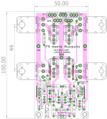
2. i see that you had kept 45mm and 50mm between mosfets, i was able to manage 44mm between o/p mosfets. is it ok now? I agree inline mosfets dissipate heat better, but 100mm PCBs are cheap to make
. 3. i don't know if i will get the mosfets from same batch, so will stick to the 0.22 ohm source res.
4. if you ever work out a new biasing scheme, i will incorporate the same.
5. Is it important to take individual feedback from the respective source resistors of Q3 and Q5 for R16 and R17 ? shown below.
reg
Prasi
Attachments
Last edited:
Here is the final layout for anyone willing to build, compatible with single sided home etching or double sided PCB manufacture.
For double sided
1. V+ and V- rails are on both sides.
2. Input ground is connected to PGND. (in case of single sided PCB one may use a separate wire.)
reg
Prasi
For double sided
1. V+ and V- rails are on both sides.
2. Input ground is connected to PGND. (in case of single sided PCB one may use a separate wire.)
reg
Prasi
Attachments
Last edited:
Nice board prasi and nice project.
Could be adopted the BJT input of the F5HA here?
It is more diy friendly newer days- JFet high priced......so on.
You should try jfets, they are hard to get and expensive, but in the scheme of things, well worth the hassle. They sound very good in this position IMO
Nice board prasi and nice project.
Could be adopted the BJT input of the F5HA here?
It is more diy friendly newer days- JFet high priced......so on.
Hi Bangla,
I am sure Juma can come up with bjt version, may be with low noise BC550/560
.But I read people prefer fets those places. Slightly OT, how is your eagle training coming along?
reg
Prasi
- Home
- Amplifiers
- Pass Labs
- F5 meets Buzquito