Bernard,
I'm really short of time this week to read the thread carefully but it seems you're cranking on the redesign. Congrats.
I meant to reference the bootstrapped follower design and Self's site but Hugh covered that one.
I've simulated a similar arrangement with differential source followers using a modulated pull-down current source. My simulation schematic is a bit messy and might do you more harm than good so I won't post it.
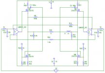
I like the Aleph current source - take a look at it. It is basically a Wilson current source but with an added virtual ground (at the base of the BJT) where the modulating current is summed.
In the Aleph case the current source is floating with the output voltage - the source (and source resistor) of the power FET are connected to the output signal. A small sensing resistor feeds back the changes of output current.
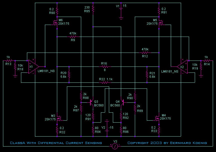
You can adopt a similar approach for a follower pull-down current. Again, a Wilson current source but this time the power FET source (and source resistor) connect to the negative supply and the power-FET drain connects to the output voltage. You can sense the output current with a resistor in the drain of the source followers (R80 & R81 in your schematic). The change in voltage across R80/81 is fed to the Aleph current source as a current through a resistance and summed in the vitrual ground. Because of the large commom-mode difference between the pull-down current source at the negative supply, and the sensing resistors (R80/81) at the psotivie supply I'd recommend ac coupling the sense current into the summing node. This means the current source will not respond to DC but that's not a bad thing so it won't pump up the current if there's an output short! Just set the corner frequency as low as you need.
Regards
13th Duke of Wymbourne
I'm really short of time this week to read the thread carefully but it seems you're cranking on the redesign. Congrats.
I meant to reference the bootstrapped follower design and Self's site but Hugh covered that one.
I've simulated a similar arrangement with differential source followers using a modulated pull-down current source. My simulation schematic is a bit messy and might do you more harm than good so I won't post it.
I like the Aleph current source - take a look at it. It is basically a Wilson current source but with an added virtual ground (at the base of the BJT) where the modulating current is summed.
In the Aleph case the current source is floating with the output voltage - the source (and source resistor) of the power FET are connected to the output signal. A small sensing resistor feeds back the changes of output current.
You can adopt a similar approach for a follower pull-down current. Again, a Wilson current source but this time the power FET source (and source resistor) connect to the negative supply and the power-FET drain connects to the output voltage. You can sense the output current with a resistor in the drain of the source followers (R80 & R81 in your schematic). The change in voltage across R80/81 is fed to the Aleph current source as a current through a resistance and summed in the vitrual ground. Because of the large commom-mode difference between the pull-down current source at the negative supply, and the sensing resistors (R80/81) at the psotivie supply I'd recommend ac coupling the sense current into the summing node. This means the current source will not respond to DC but that's not a bad thing so it won't pump up the current if there's an output short! Just set the corner frequency as low as you need.
Regards
13th Duke of Wymbourne
Hi Bernhard,
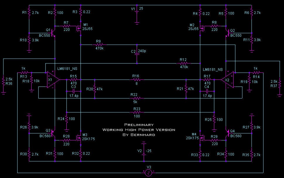
I have examined the design, and it looks pretty good to me. I'm a little confused at the 470K resistor from the output back to the non-inverting point; it would appear to be positive feedback, or is it somehow related to offset control (can't see why, though).
However, I have misgivings about the complex DC voltage shifter you have implemented to overcome the perceived shortcoming of using a 1R5 sense resistor. I've partially followed the Duke's comments about Wilson current mirrors, which are very clever gadgets - more tricks than a monkey on a mile of jungle vine - but the level shifter worries me.
Let's examine this. As the current falls in the upper mosfet, the voltage at the current sense rises. This positive pulse travels through the cap to the gate of the lower mosfet, and kicks up the current. The measure of current increase is dictated by three things for a given current increment; the size of the upper sense resistor, the transconductance of the lower mosfet, and the size of the current setting resistor in the lower mosfet. Rather than increase the upper resistor, it makes sense to me to reduce the current setting resistor, since most n-channel mosfets will have a transconductance in excess of 7 amps per volt. Let's use a 1A quiescent, dropping to 0.5A. Across an upper sense resistor of 0R47 - the size I choose - the voltage will rise 0.235V, PLUS any rise at the rail because it's now less heavily loaded. By my reckoning, even if only 0.2V of this pulse reaches the lower mosfet due to the loading of the gate stopper, at 7S this would raise the current through the lower mosfet, with say a 0R33 current sense resistor, from 1A to around 1.5A, which is pretty much lineball, and might even need watering down by increasing the value of the current setting resistor at the lower mosfet. BTW, these figures take proper account of the increase in voltage drop across the current setting 0R33 resistor, too.
If this does not check out on PSpice, then fer crissakes build the bugger and MEASURE it rather than rely on PSpice, which I have always regarded as a flight simulator anyway, useful for training, but hardly the real thing....
The elegance of your SS level shifter is unmistakeable. BUT, for reasons outlined earlier, the use of an electrolytic does not interfere with sonics, and the introduction of a further level of SS complexity, with gain moreover, introduces the unpalatable prospect of stability and unreliability.
I don't wish to pour cold water on this, Bernhard, but it's very clever, particularly the way in which you route the feedback signal. Nonetheless, how about single ended beast with more attention to trimming the quiescent to the absolute minimum to avoid switching, to foster the prospect of a little H2, Count? (A name I feel is appropriate after seeing your positively Transylvanian animated icons atop the page!)
Cheers,
Hugh
Duke, Hugh,
honestly I never tried to understand the Aleph current source and it is a mistery to me why it has even two caps.
One reason for this is the secret fact that often it is better not to know too much about what others have done before, which means to be able to look at things like a child who has little knowledge, this can pretend the tunnel effect.
Maybe its time now for me to have a close look at Nelson's masterpiece.
Anyway, the complicated level shifter works well on the sim, as does the whole circuit.
Before -you all were right- with the inductive load, the currents through the master and slave Fets were out of phase.
Now with the level shifter that bug is fixed.
The level shifter gives me the advantage that I can use the small source/drain resistors of 0.22ohm and that the grade of modulation is adjustable exactly to 100%, so that the currents through the fets are symmetric/equal.
Greetings, Bernhard
Hugh,
again, what is SS amplifier/complexity ???
and also this I don't understand: trimming the quiescent to avoid switching ??? to the absolute minimum to foster the prospect of a little H2 ??? Count?
Comparators LM339 across the source/drain resistors could shut down the amp in case of a short.
There was a very interesting cfb op amp with a bias control pin that can also be used to shut down the amp.
and also this I don't understand: trimming the quiescent to avoid switching ??? to th
Bernhard,
I'm sorry; I guess I'm using slang/idiom, not fair. When I think how woeful my German is, I am ashamed.
SS is simply Solid State.
Complexity is something which reduces simplicity, and thus makes it more difficult to tune, and make reliable.
Bernhard,
I'm sorry; I guess I'm using slang/idiom, not fair. When I think how woeful my German is, I am ashamed.
again, what is SS amplifier/complexity ???
SS is simply Solid State.
Complexity is something which reduces simplicity, and thus makes it more difficult to tune, and make reliable.
Hi Bernhard,
Now for the second explanation:
In a Class A push pull amplifier neither output device ever switches off. This is not true of a Class AB or Class B amplifier, and many people say they can hear the switching, as each side alternately switches on, then off, then on again.
If we try to get a Class AB amplifier to do Class A tricks, we certainly want each output device to remain on, no matter how little, all the time.
The Pass Current Source does this. It holds the inactive device on at all times, under tight control, so that it never switches off.
The tighter this control, then the lower we can set the quiescent, improving efficiency.
The greater the current variation through a device, then the more will be the variation in bias. For a bipolar transistor, this means Vbe, for a mosfet, Vgs.
The more variation there is in the current through a device, then the greater is the bias variation, and therefore the greater is the level of asymmetrical distortion produced. This is second harmonic by definition. We know that the upper mosfet controls the sonics - effectively the transfer characteristics of the amplifier - and the current sink just draws up the rear. It is supporting infrastructure; nothing more.
Of course, in your design you have lots of global negative feedback. Thus any distortion, of any type, will be corrected to a large extent; nonetheless, asymmetric distortion will only be reduced by the feedback factor, which is finite, and thus if we trim back the quiescent to the absolute minimum to achieve high efficiency, we can expect a little distortion to get past the feedback correction.
Cheers,
Hugh
Now for the second explanation:
and also this I don't understand: trimming the quiescent to avoid switching ??? to the absolute minimum to foster the prospect of a little H2 ??? Count?
In a Class A push pull amplifier neither output device ever switches off. This is not true of a Class AB or Class B amplifier, and many people say they can hear the switching, as each side alternately switches on, then off, then on again.
If we try to get a Class AB amplifier to do Class A tricks, we certainly want each output device to remain on, no matter how little, all the time.
The Pass Current Source does this. It holds the inactive device on at all times, under tight control, so that it never switches off.
The tighter this control, then the lower we can set the quiescent, improving efficiency.
The greater the current variation through a device, then the more will be the variation in bias. For a bipolar transistor, this means Vbe, for a mosfet, Vgs.
The more variation there is in the current through a device, then the greater is the bias variation, and therefore the greater is the level of asymmetrical distortion produced. This is second harmonic by definition. We know that the upper mosfet controls the sonics - effectively the transfer characteristics of the amplifier - and the current sink just draws up the rear. It is supporting infrastructure; nothing more.
Of course, in your design you have lots of global negative feedback. Thus any distortion, of any type, will be corrected to a large extent; nonetheless, asymmetric distortion will only be reduced by the feedback factor, which is finite, and thus if we trim back the quiescent to the absolute minimum to achieve high efficiency, we can expect a little distortion to get past the feedback correction.
Cheers,
Hugh
AKSA said:This is not true of a Class AB or Class B amplifier, and many people say they can hear the switching, as each side alternately switches on, then off, then on again.
If we try to get a Class AB amplifier to do Class A tricks, we certainly want each output device to remain on, no matter how little, all the time.
The Pass Current Source does this. It holds the inactive device on at all times, under tight control, so that it never switches off.
The tighter this control, then the lower we can set the quiescent, improving efficiency.
The more variation there is in the current through a device, then the greater is the bias variation, and therefore the greater is the level of asymmetrical distortion produced. This is second harmonic by definition. We know that the upper mosfet controls the sonics - effectively the transfer characteristics of the amplifier - and the current sink just draws up the rear. It is supporting infrastructure; nothing more.
Of course, in your design you have lots of global negative feedback. Thus any distortion, of any type, will be corrected to a large extent;
Hi Hugh,
Do you refer to the circuit with sliding bias and single ended classA or the other one or both ???
this is the Aleph with and without active current source, it is clear that all devices remain on at all times:
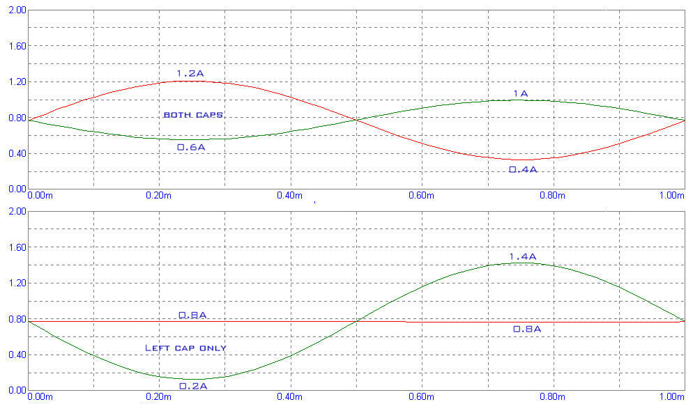
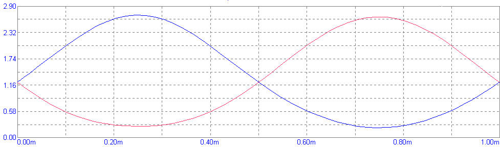
Now in the attached picture of the next post (sorry for the confusion...) you see that the currents also never go below 200mA per device even at full or no input signal.
Is that ClassAB or B and is there switching which might be audible ?
The graph belong to this circuit:
You say that the Aleph CS let all devices always stay on.
My Circuit with sliding bias and level shifter does the same except at clipping, but this is also with the Aleph CS.
And it must be like this, idle through each device is about 1.4A, so how should it ever turn off ???
What if we let the master Fet swing 1A and the slave swing 2A or 3 A ?
The bias variation of the upper mosfet which controls the sonics will be small...
And the variation of the lower fet high.
nonetheless, asymmetric distortion will only be reduced by the feedback factor, which is finite, and thus if we trim back the quiescent to the absolute minimum to achieve high efficiency, we can expect a little distortion to get past the feedback correction.
[/B]
So you mean, if I make the idle current as small as possible there will be distortion because the feedback can not correct everything ?
This is also a supersymmetric circuit in which according to Nelson, nearly every distortion shall cancel out between left and right side.
Greetings, Bernhard
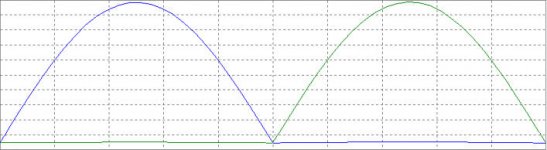
These are the currents through the upper and lower fets just before clipping.
The clipping will be because of the driving op amp, not because of the CS running out of current...
belonging to the sliding bias single ended classA
Nelson writes that the Alephs sound better with more bias.
This could be an explanation:
On full input signal, one of the two Fets carries only little current, around 200mA, if the idle is higher, also the remaining current at full signal will be higher, providing better linearity.
AKSA said:In a Class A push pull amplifier neither output device ever switches off. This is not true of a Class AB or Class B amplifier, and many people say they can hear the switching, as each side alternately switches on, then off, then on again.
If we try to get a Class AB amplifier to do Class A tricks, we certainly want each output device to remain on, no matter how little, all the time.
The Pass Current Source does this. It holds the inactive device on at all times, under tight control, so that it never switches off.
The tighter this control, then the lower we can set the quiescent, improving efficiency.
I would like to note that this is an accurate description of the
dynamic bias scheme found in the 1975 Threshold 800A. As an
approach, I retired this concept in 1977, and since then I prefer
loosely controlled active current sources, as seen in the actual
Aleph circuits. If you use the current source to get performance
from low bias values, you end up with the same crap as the
imitators of the 800A, which used the concept to idle the circuit
at .1 amps instead of 2 or 3 amps.
It would seem that you simply can't fool Mother Nature; if you
want the Class A sound, you must idle at near Class A currents.
In the case of Aleph current sources, we find that as we reduce
the bias currents, we lose the effect we want. That's why the
800A and its successors (including the X amps) idled at 100
of rated output, and the Alephs (and XAs) idle at 300% of
rated output.
There's just no free lunch, not even from transistor salesmen...
Hi Nelson,
Thank you for offering this gem; I must admit it doesn't surprise me, as Mother Nature abhors a compromise..... I had my suspicions how far we could take this too, and had set my design at around 1.4A, using fan cooling.
I am astonished, and somewhat aghast, that you came up with this in 1975, and here we are full circle. Not much new under the Sun, huh? It would be a brave man disagrees with you, Sir!
Bernhard, there's the rub; you use tight control, trim bias to 100mA, and suffer the sonic consequences. Loosen control over the current sink, and all is well. Perhaps the next challenge might be to devise a circuit which DOES yield good sound at vanishingly low quiescent settings. That is clearly where you should be heading in this relentless search for teutonic efficiency
Perhaps an AKSA?
Cheers,
Hugh
AKSA said:I had my suspicions how far we could take this too, and had set my design at around 1.4A, using fan cooling.
you use tight control, trim bias to 100mA, and suffer the sonic consequences.
Perhaps the next challenge might be to devise a circuit which DOES yield good sound at vanishingly low quiescent settings. That is clearly where you should be heading in this relentless search for teutonic efficiency
Hi Hugh,
the single ended will be at 1.2A for the moment.
And the normal at 200mA.
I just said that I heard that the lateral fets have good linearity from 100mA, not that I will go that low.
Yes I am looking for the 100mA classA sound amp

Because of the 8 amps that I need.
But maybe I am not looking for the classA sound amp.
I want clean distortion free sound, not sweet 2nd order harmonic distortion.
Or maybe that sounds nicer ?
I don't know what I want.
So I will built the classA and compare it to the 200mA.
Greetings, Bernhard
We must be misunderstanding each other. The dynamic biasAKSA said:I am astonished, and somewhat aghast, that you came up with this in 1975, and here we are full circle. Not much new under the Sun, huh? It would be a brave man disagrees with you, Sir!
circuit was 1975, and as I indicated, corresponds closely with
your description. The Aleph circuit, which is a single-ended
current source comes from about 1991, and doesn't offer what
I would call tight control, doesn't allow lower idle than 1/2 peak,
and doesn't keep the gain device from going into shutoff when
overdriven. It does, however, sound better IMHO.
No, no, Nelson, I understood all right!
You clearly stated the control system was tight back in '75, but did not sound as good as the loose CS at half Class A quiescent levels.
I find myself wondering why; maybe at the lower quiescents the variation in Vgs is so much larger that there is too much H2, at least in the SE mode?
In that event, something with a more uniform step function than a simple source follower might be the ticket. This would enable tighter control and thus superior efficiency without throwing away the sonics?
Cheers,
Hugh
Hi Rod,
That's a damn good point, and thanks for making it! Thermal cycling, I believe it's called??
If we think on NP's comment about sounding better, then, all other things being equal, it focuses attention on the relationship between input and output on the power follower circuitry. This should ideally be a simple step function, in the case of a source follower, the Vgs of the output device.
It is clearly the distortion introduced at this point which causes this perceived difference in quality, but the question is what sort of distortion is this?
If we use a reasonably fast chip and feedback network, it's reasonable to assume that H2 and H3 will be pretty much removed, but that the higher harmonics will be progressively less reduced. (Note that I'm essentially ignoring the input chip and any intermodulation produced by the feedback network, and that could be a mistake, but hell, one thing at a time). Consequently, the difference might just be higher order harmonics - and I'm making assumptions here of course - but if so, then this comes back to the transfer function of the active device. It may be that thermal cycling and/or simple source follower circuits introduce higher level harmonics, and this situation is ameliorated by increasing bias levels so that the variation in Vgs is less, leading to greater linearity.
I have to say that I have never built an amplifier - not ever - which did not sound better when I improved the linearity. This fact has emerged over many years, and seems to lend credibility to the math/measurement approach, but I do believe there is something more to it than this. Alas, I have not the math to verify or dispute these empirical findings, but by talking long and loud in this forum I keep hoping someone will lead me to the Holy Grail.........
Cheers,
Hugh
Hi Hugh,
Good to see / read your posts...sheer joy.
I'm not buying into the tech side of this thread, but my own observations suggest and reinforce what is being said here, that is these class A designs have a few interesting pecularities.
They sound best when warmed up (say 1 hour), there appears to be an optimium voltage drive where they deliver the most resolution, and as you increase the bias everthing about the sound improves. One assumes linearity is related to these issues?
The wisdom of common sense & logic is however often lost in the mosaic modern science.
From my own empirical view point all this suggests the bias must be at a steady state level to pass (no pun intended) the required current for normal operation ( under signal drive), and that large peak demands could then be given a healthy swing of more current, or move to A/B (rather than from milliamps to amps).
The flip side is how to deliver low distorion with minimal negative feedback.
This appears to be born out in the highly respected Passlabs X Series.
macka
Bernhard said:This could be an explanation:
On full input signal, one of the two Fets carries only little current, around 200mA, if the idle is higher, also the remaining current at full signal will be higher, providing better linearity.
Look at the picture, @75°C the transfer function of this N-fet is perfectly linear between 2A and 6A, so it would be best if the current would swing around 4A idle point.
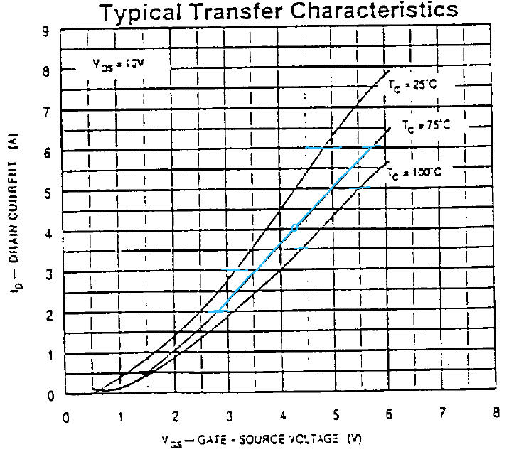
That also explains why the amp sounds better when warmed up, the transfer function is not linear @25°C @ same currents.
If the idle is 2A, the first few watts will be the best because the currents remain still in the linear area.

The higher the output power gets, looking on one fet, the more one "halfwave" (2A and higher) gets even more into the linear region
, but the other halfwave (2A and lower) gets into the nonlinear region  , so no wonder that the last few watts are the poorest
So, if I'm right this is nothing about voodoo.
Got some fresh ideas
Bernhard
- Status
- This old topic is closed. If you want to reopen this topic, contact a moderator using the "Report Post" button.
- Home
- Amplifiers
- Pass Labs
- X = bridged = push pull ? ...