Thank ijomojo for point out to us that Semisouth have a new 1700V SiC JFET SJEP170R550!
With a fair amount of effort, I managed to get through their automatic answering machine system, and got a quote.
The cost of this new 1700V Jfet is about 75% of that of SJEP120R100, and the SJEP120R063 being much more expensive.
Since the SJEP120R125 is obsolete, and SJEP120R063 very expensive, I sees the SJEP120R100 (the subject of Magura's GB) and this SJEP170R550 as the best candidate for DIYers.
Power handling
The SJEP170R550 has thermal resistance RTHjc of 2.6degC/W, while both SJEP120R100 and R125 are rated 1.1degC/W.
If the insulation mounting of their TO-247 to heatsink (plus the heatsink local spreadout resistance) has a RTH of 0.4degC/W, then they will have a total RTH(junc to heatsink) of 3.0 and 1.5.
In this case the R100 and R125 has double the power capability of the new part.
A more relistic figure of the mounting will be 1degC/W, is that case (1.1+1)/(2.6+1)=58%, which means the SJEP170R550 should be able to handle about 58% of the R100/R125 power.
Transconductance
The semisouth datasheet only has graph of ID vs VGS (Figure 6) but no conductance vs ID curve.
So I spend some effort to manually measured the conductance (under extreme enlargement in photoshop) at ID of our interest.
The transconductance are found to be:
SJEP170R550
Papa's J2 is rated for 30W at 8ohm and 15W at 4ohm, from this it is not hard to calculate that the bias current through each JFET is about 1.4A.
If we use SJEP120R100, we will just keep the 1.4A, and with SJEP170R550 we can go to 0.8A without increasing juction temp.
We can see that a single SJEP170R550 has 80+% of the transconductance of a single SJEP120R100.
Two parallel SJEP170R550 will have much higher transconductance than a single SJEP120R100, and reach about 85-90% of that of J2's single SJEP120R125.
SJEP120R100's ID leakage at low VGS?
From the ID vs VGS graph of SJEP120R100, the ID does not totally shut off at VGS<1V. between 0.3V<VGS<0.8V, the ID is flat at 0.78A.
And the slope (=transconductance) is seems abnormally gentle until VGS pass 0.9V or so.
This is only seen in the SJEP120R100 and no where else in Semisouth's other JFET.
I guess this will means the first 0.75A bias current through the SJEP120R100 is wasted. Anyone has a better idea?
Gate capacitance
It is very difficult to read off the graph due to the voltage scale.
We can roughly see that, at the very low end of the VDS:
SJEP170R550 shows Ciss of up to 400pF
SJEP120R100 shows Ciss of up to 1200pF
The datasheet gives Ciss:
SJEP170R550 170pF@300V (from graph: <180pF@100V)
SJEP120R100 670pF@100V
SJEP120R125 610pF@100V
If their gate capacitance curve are of the same shape (a linear multiple of one another), then at low VDS SJEP170R550 will still keep a 1:4 Ciss advantage over SJEP120R100
Conlusion: the SJEP170R550 has roughly 1/3 or SJEP120R100's Ciss, and the linearity of the gate capacitance is too hard to tell.
Overall
It is such a pity that SJEP120R125 is no longer produced (and guess who has stockpile of it?), as SJEP120R100 does not seems to be as good and it takes 2x SJEP170R550 to get near its performance.
Between the SJEP170R550 and SJEP120R100, from what I can see the SJEP170R550 seems to be more useful.
The only obvious problem I can see in the SJEP170R550 is that its ID vs VDS curve for VGS=1.5V seems to be more flat, suggesting it is less capable of taking advantage of loadline cancellation.
I'm sure I missed out a lot of point, so pls help me to bring them out.
With a fair amount of effort, I managed to get through their automatic answering machine system, and got a quote.
The cost of this new 1700V Jfet is about 75% of that of SJEP120R100, and the SJEP120R063 being much more expensive.
Since the SJEP120R125 is obsolete, and SJEP120R063 very expensive, I sees the SJEP120R100 (the subject of Magura's GB) and this SJEP170R550 as the best candidate for DIYers.
Power handling
The SJEP170R550 has thermal resistance RTHjc of 2.6degC/W, while both SJEP120R100 and R125 are rated 1.1degC/W.
If the insulation mounting of their TO-247 to heatsink (plus the heatsink local spreadout resistance) has a RTH of 0.4degC/W, then they will have a total RTH(junc to heatsink) of 3.0 and 1.5.
In this case the R100 and R125 has double the power capability of the new part.
A more relistic figure of the mounting will be 1degC/W, is that case (1.1+1)/(2.6+1)=58%, which means the SJEP170R550 should be able to handle about 58% of the R100/R125 power.
Transconductance
The semisouth datasheet only has graph of ID vs VGS (Figure 6) but no conductance vs ID curve.
So I spend some effort to manually measured the conductance (under extreme enlargement in photoshop) at ID of our interest.
The transconductance are found to be:
SJEP170R550
0.7A 3.23S
1.0A 3.78S
SJEP120R100:1.0A 3.78S
1.4A 3.96S
2.0A 6.05S
SJEP120R125(obsolete):2.0A 6.05S
1.4A 7.85
2.0A 10.4
2.0A 10.4
Papa's J2 is rated for 30W at 8ohm and 15W at 4ohm, from this it is not hard to calculate that the bias current through each JFET is about 1.4A.
If we use SJEP120R100, we will just keep the 1.4A, and with SJEP170R550 we can go to 0.8A without increasing juction temp.
We can see that a single SJEP170R550 has 80+% of the transconductance of a single SJEP120R100.
Two parallel SJEP170R550 will have much higher transconductance than a single SJEP120R100, and reach about 85-90% of that of J2's single SJEP120R125.
SJEP120R100's ID leakage at low VGS?
From the ID vs VGS graph of SJEP120R100, the ID does not totally shut off at VGS<1V. between 0.3V<VGS<0.8V, the ID is flat at 0.78A.
And the slope (=transconductance) is seems abnormally gentle until VGS pass 0.9V or so.
This is only seen in the SJEP120R100 and no where else in Semisouth's other JFET.
I guess this will means the first 0.75A bias current through the SJEP120R100 is wasted. Anyone has a better idea?
Gate capacitance
It is very difficult to read off the graph due to the voltage scale.
We can roughly see that, at the very low end of the VDS:
SJEP170R550 shows Ciss of up to 400pF
SJEP120R100 shows Ciss of up to 1200pF
The datasheet gives Ciss:
SJEP170R550 170pF@300V (from graph: <180pF@100V)
SJEP120R100 670pF@100V
SJEP120R125 610pF@100V
If their gate capacitance curve are of the same shape (a linear multiple of one another), then at low VDS SJEP170R550 will still keep a 1:4 Ciss advantage over SJEP120R100
Conlusion: the SJEP170R550 has roughly 1/3 or SJEP120R100's Ciss, and the linearity of the gate capacitance is too hard to tell.
Overall
It is such a pity that SJEP120R125 is no longer produced (and guess who has stockpile of it?), as SJEP120R100 does not seems to be as good and it takes 2x SJEP170R550 to get near its performance.
Between the SJEP170R550 and SJEP120R100, from what I can see the SJEP170R550 seems to be more useful.
The only obvious problem I can see in the SJEP170R550 is that its ID vs VDS curve for VGS=1.5V seems to be more flat, suggesting it is less capable of taking advantage of loadline cancellation.
I'm sure I missed out a lot of point, so pls help me to bring them out.
Last edited:
Found this article saying J2 uses R100, but 6moon's photo shows J2 uses the now obsolete R125. So which is correct?
In practice there is very little difference between the R100 and
R125 versions for our applications. I get just about the same
numbers in the J2's with either part.

Thanks Papa!
Your words are more worthy than their datasheet!
Hi Nelson,
I'm really looking forward to see the J2 Circuit being released. Hopefully before Magura spreads out the parts... ;-)
Maybe a circlotron J2 would be very interesting. (I know, there's a version out there, but I would like to see a comparision of the specs between the Nelson optimised version, and the semisouth drop in approach.
Looking at the specs of the drop in semisouth version, it looks like a stronger driver required...
Regs, Dirk
P.S.: Your passdiy website is not reachable... ;-(
.....
Since the SJEP120R125 is obsolete, and SJEP120R063 very expensive, I sees the SJEP120R100 (the subject of Magura's GB) and this SJEP170R550 as the best candidate for DIYers........
I'm sure I missed out a lot of point, so pls help me to bring them out.
considering results of your photoshoping , and counting also on what I raped my eyes in last two days ,I'm pretty sure that we must use 2 paralleled 550's in every position , if we want nice characteristics and safe operation in same time , at least in voltage/current ranges interesting to common Papa's follower/spoiled kid ;
so - counting on words written by greatest kid of all kids prisoned in mature envelope :
.......
With regard to JFETs, there are more parts coming out in
time, so patience will be rewarded.
....... I think that's wisest to hold your horses for some short period , at least while Papa spill few more breadcrumbs on table ......
you know familiar feeling - there is always better tube just around the corner

considering results of your photoshoping , and counting also on what I raped my eyes in last two days ,I'm pretty sure that we must use 2 paralleled 550's in every position.
Yes, I was thinking of having two r550 to replace one r125. But two 550 is 50% more expensive than one of the already not cheap r100, plus I expect the change of JFET will be unappealing to a large part of this community, making large qty order infeasible and thus even higher price.
Now that knowing r100 is also an official J2 part, the option looks clear.
Until Papa said:
With regard to JFETs, there are more parts coming out in
time, so patience will be rewarded.
Is semisouth or someone else having a much greater product around the corner?
SiC JFET in new packaging and withstand 400degC?
Or much cheaper alternatives?
Higher and more linear Gm?
Please enlight me a little more!
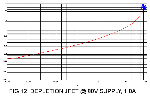
Take a look at the last curve in "De-Lite"
baaad Papa ! baad !
( will it drive F4 ?
 )
)next jfet :
In simple noob terms
Hi,
As a noob who will be mostly following instructions and parts reccommendations on others, can someone speak in non-technical terms to whether there are instances in which the R550 might be prefereable to the other SemiSouth chips? My speakers are ~97dB efficient, so I need minimal power.
Hi,
As a noob who will be mostly following instructions and parts reccommendations on others, can someone speak in non-technical terms to whether there are instances in which the R550 might be prefereable to the other SemiSouth chips? My speakers are ~97dB efficient, so I need minimal power.
It will probably work fine. I haven't received any samples of
that yet, but I expect somewhat higher thd numbers, but lower
input capacitance, so it will be more forgiving of the impedance
of the source driving it.
Of course the real excitement is the 1700 V breakdown figure,
which would allow you to stick it where many tubes will not go.
that yet, but I expect somewhat higher thd numbers, but lower
input capacitance, so it will be more forgiving of the impedance
of the source driving it.
Of course the real excitement is the 1700 V breakdown figure,
which would allow you to stick it where many tubes will not go.
Nelson,
Can you share with us, why do you think the THD number will be higher?
Is it because it has lower transconductance, and thus higher distortion on a chip to chip basis?
If the above is right, any insights on how well it works, given equal transconductance by paralleling.
I'm also thinking, whether R550 will be good for replacing the IRF610 in D1 DAC's I/V stage.
Zhou Fang
All other things equal, chips with low transconductance will
have greater thd, the reason being that the nonlinearity of
Vgs vs Id will be greater.
That said, the best way to find out what you will get with a
real application is to actually try it. I don't have any of this
part, and so I have not tried it.
have greater thd, the reason being that the nonlinearity of
Vgs vs Id will be greater.
That said, the best way to find out what you will get with a
real application is to actually try it. I don't have any of this
part, and so I have not tried it.
It will probably work fine.
Did you check the SJEP120R100 maybe? I've compared all specs and does NOT seem a perfect drop-in of the R125.
All other things equal, chips with low transconductance will
have greater thd, the reason being that the nonlinearity of
Vgs vs Id will be greater.
That said, the best way to find out what you will get with a
real application is to actually try it. I don't have any of this
part, and so I have not tried it.
Thanks for the answer!
I get it, so it is just the lower transconductance that caused your expectation of higher THD.
It is sad that R125 is no longer available.
My fear is that (as others has pointed out), when they can mass-produce SiC MOSFET, will there still be any SiC power JFET available for us?
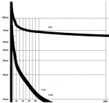
Here is the SS-R100 capacitances graph attachment.
I have this graph in the pdf expanded and enchanced it with the additional
10V grid lines (by dividing 300V in 30 equal segments).
It has also thickened the curves, but it's not a problem.
Zero V vertical line was assigned to the left edge of the thick line.
I have this graph in the pdf expanded and enchanced it with the additional
10V grid lines (by dividing 300V in 30 equal segments).
It has also thickened the curves, but it's not a problem.
Zero V vertical line was assigned to the left edge of the thick line.
Attachments
- Status
- This old topic is closed. If you want to reopen this topic, contact a moderator using the "Report Post" button.
- Home
- Amplifiers
- Pass Labs
- Semisouth SiC JFETs: SJEP120R100 or SJEP170R550 better for building amp?