Pass DIY Addict
Joined 2000
Paid Member
Please help me learn something.
I just installed a CL-60 thermistor in series with the primary leg of the transformer on my A40 amp and noticed that the mechanical buzz from the transformer has been reduced.
The amp is powered by a 600VA transformer (custom wound by Victoria Magnetics some years ago) that feeds two channels, each of which draws about 3.2A from 32v rails. The transformer has always had a small buzz to it, but now it is much less. With the thermistor in place, the rail voltage drops about 0.5v DC (I expected some drop - this is not a problem).
Why does installing the thermistor reduce mechanical buzz?
Thanks,
Eric
Reduced buzz
Hi Eric,
As you have placed a thermistor in series with the primary you have reduced the voltage and current through the primary.
It is possible that without the thermistor there was too much voltage/current on the primary causing the core to saturate and buzz.
I have found this problem to be very common in the UK where items brought in from abroad are wound for a nominal 230Vac whereas in the UK the nominal line voltage is 240Vac or higher in a lot of cases. One customer of mine regularly measures his line voltage at 253Vac so we have put a couple of Thermistors in series to cut this down and also reduce the switch on "surge"
John Caswell
One reason is the thermistor prevents at turn-on the initial large surge (then constant after a while for Class A A40) of current demanded by your power supply/amp...the other is the equivalent R of your thermistor is dropping some of the DC voltage present on your primaries.
Pass DIY Addict
Joined 2000
Paid Member
Hmmm... This is curious. At one time I did build and install a DC blocker on the transformer primaries thinking that was the cause of the buzz, but it had no effect, so I removed it.
Measuring the wall outlet, I'm getting a pretty consistent 126v whereas the transformer is designed for 120v. The thermistor drops about 0.6-0.7 VAC to the transformer, so it could indeed be at/near saturation without it.
Thanks!
Eric
Measuring the wall outlet, I'm getting a pretty consistent 126v whereas the transformer is designed for 120v. The thermistor drops about 0.6-0.7 VAC to the transformer, so it could indeed be at/near saturation without it.
Thanks!
Eric
Pass DIY Addict
Joined 2000
Paid Member

Measuring the wall outlet, I'm getting a pretty consistent 126v whereas the transformer is designed for 120v. The thermistor drops about 0.6-0.7 VAC to the transformer, so it could indeed be at/near saturation without it.
Thanks!
Eric
Hi Eric, I don't think that the extra 6 Volts (only 5%....) causes the saturation(?)/buzz of the toroid. A common problem in the EU is odd harmonics on the neutral conductor. For 50 Hz mains these are mainly 150Hz and 250Hz, caused by switched-power stuff and make high mu cores saturate.
One of your own finding confirms this; drawing 2A through the CL60; with a voltage drop would only dissipate:
P=UxI = 0.7 x 2 = 1.4W while your CL60 is near boiling point...
You can try to borrow a poweranalyser and check the harmonics on the Live and Neutral lines.
Adding extra thermistors in series only lowers your Circuit impedance, resulting in less "control" and peak current flowing through the power supply.
I always short my thermistors with a power relay after rush in.
Succes!
Schematic of your layout please ......
Schematic of your layout please ......
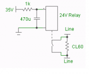
Well, here's the least safe one (the 24V relay is direct on the mains with a voltage divider)
Much safer is the use a small transformer for the inrush limiters
BTW in this schematic there are powerR's instead of thermistors

Last edited:
And here's the more safe version
Nb. only the relay contacts are shown, they are supposed to short the thermistor.
View attachment inrush.bmp
Nb. only the relay contacts are shown, they are supposed to short the thermistor.
View attachment inrush.bmp
Pass DIY Addict
Joined 2000
Paid Member
Thanks for the schematic. I'm interested in giving it a try as the thermistor adds a good deal of heat to the inside of the chassis.
The entire amplifier draws 2A from the wall at ~120v, the thermistor is in series with the primary leg of the transformer. Seemed strange to me that it gets so hot, but I've heard lots of account of them getting very hot, so it didn't really cause any concern.
If I short the legs of the thermistor after the amp is up and running, the level of buzz does come back.
Interesting. I've used Thermisters for years as surge suppressors, a CL-60 (or 2 in series) placed in the primary for turn on and bypassed via relay actuation after about 5 seconds. There is sometimes an increase in mechanical noise after the bypass and I say to myself "what the heck, did the thermister(s) not have time to decrease to a low value during the startup?"
So you leave it in and no problems? Is it safe to run it that hot?
So you leave it in and no problems? Is it safe to run it that hot?
Thanks for the schematic. I'm interested in giving it a try as the thermistor adds a good deal of heat to the inside of the chassis.
The entire amplifier draws 2A from the wall at ~120v, the thermistor is in series with the primary leg of the transformer. Seemed strange to me that it gets so hot, but I've heard lots of account of them getting very hot, so it didn't really cause any concern.
If I short the legs of the thermistor after the amp is up and running, the level of buzz does come back.
Weird. I use thermistors in my amp and they do not run hot at all, I use one for hot and one for neutral on the primaries.without them my fuses pops (5A).My power supply is 670vac 35ac X2 40000uf total using mur860 X8. I use from Ametherm SL22 2R515.
using two nxv200 (stereo) from Aussie amplifiers.
And here's the more safe version
Nb. only the relay contacts are shown, they are supposed to short the thermistor.
View attachment 156905
I've used a transistor switch like that, but lately, I just do this one. Fewer parts (relay, resistor, cap), works fine. Relay in this example has series resistance of about 1k. It's just powered from B+. The CL device is in the neutral line.
Sheldon
Attachments
Pass DIY Addict
Joined 2000
Paid Member
Sheldon: thanks for the schematic - I like the simplicity.
Lanchile: There may be a few difference in the characteristics of the thermistors themselves, and the NXV200 does not have the same current draw as Class-A amps, so there is a large inrush at powerup to charge the caps after which current draw declines substantially. The A-40 and my Aleph-X amps (they both run pure Class-A) have sustained high current draw after initial powerup. I think this is probably the bigger difference.
Lanchile: There may be a few difference in the characteristics of the thermistors themselves, and the NXV200 does not have the same current draw as Class-A amps, so there is a large inrush at powerup to charge the caps after which current draw declines substantially. The A-40 and my Aleph-X amps (they both run pure Class-A) have sustained high current draw after initial powerup. I think this is probably the bigger difference.
Pass DIY Addict
Joined 2000
Paid Member
Those couple of W won't make a difference to you.
You gotta keep it real. You have like 300W of heat. Now including the thermistors, you got 303W")
If you're trying to reduce the temp inside the chassis, the one and only way to do so, is bigger heatsinks.
If you take a look at my latest amp, you'll see a massive overkill of heatsinking, to achieve exactly that. That amp is running around 9C above ambient.
If you don't want to go overboard in heatsinking, and thermal management in general, just be happy with the usual 25 or 30C above ambient.
Magura
You gotta keep it real. You have like 300W of heat. Now including the thermistors, you got 303W
If you're trying to reduce the temp inside the chassis, the one and only way to do so, is bigger heatsinks.
If you take a look at my latest amp, you'll see a massive overkill of heatsinking, to achieve exactly that. That amp is running around 9C above ambient.
If you don't want to go overboard in heatsinking, and thermal management in general, just be happy with the usual 25 or 30C above ambient.
Magura
Pass DIY Addict
Joined 2000
Paid Member
Ha! Thanks for putting things into perspective. I tend to get carried away with obsessing details. Where have you posted pics of your latest project? I'm curious to see.
I have been re-thinking things a little with my Aleph-X amps, though. I was planning on having each chassis built from 4 pieces of my 6.5" x 10" heatsink. This provides somewhere near 0.09-0.10 c/w of total heatsinking and results in total thermal rise of about 33c above ambient and final heatsink temp of about 50c.
After playing around, I am contemplating reconfiguring the amps with 6 sinks instead of 4. This will make each chassis larger and give me 50% more radiating area to spread the heat and provide something closer to 0.06 c/w and 20c rise for a final temp of 40c.
Eric,
Your thermistors will last pretty much forever, even without bypassing, as long as you don't exceed their ratings.
Magura
True, it's overkill for a class A amp, probably even for class AB, but in the latter case it's conceivably audible.
Sheldon
- Status
- This old topic is closed. If you want to reopen this topic, contact a moderator using the "Report Post" button.
- Home
- Amplifiers
- Pass Labs
- Why does a terminstor reduce transformer buzz?