Has anyone done an F5 SPICE simulation?
One with "good" models for the active devices?
I'd be very curious to see what that comes out looking like, especially WRT "good" models of the various output devices and the effect of trimming and matching...
I'd maybe give it a shot (I'm not a sophisticated SPICE user) if I had "good models" to run with it.
Anyone already do this? Or want to??
_-_-bear
I wouldn't trust spice as far as fine details like matching are concerned. Properties like manufacturing tolerances are hard to simulate in detail. Anyway, I don't see what you would like to match in that amp? N to P? Not much point if you use Fairchild or IRF parts.
Of course feel free to experiment, much more likely to give reasonable results than simulation in this case.
Oh and please tell me if suddenly high quality models appear somewhere on the net...the ones I have at hand are mediocre at best.
Have fun, Hannes
Of course feel free to experiment, much more likely to give reasonable results than simulation in this case.
Oh and please tell me if suddenly high quality models appear somewhere on the net...the ones I have at hand are mediocre at best.
Have fun, Hannes
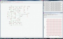
F5 Sim example
See picture.
Trimming and matching yield very low output offset.
"Good models" equ "can of worms"
The models used give a decent approximation of performance of the topology.
Real mosfet parameters vary all over the place. That's why we match and select.
A sim gives me a good idea where and how to apply a compensation cap if
required.
Clipping behavior of the amp is also easily checked.
This list could go on.
I hope this helps.
Attachments
Simulating stability is nice and gives an idea of what to expect. I wouldn't trust anything more sophisticated. Just try to simulate e.g. the Aleph30 and have a look at damping factor, frequency responce and distortion - and compare that to the published measurements.
You will see what I mean.
But of course I will stop now, this should not become a spirit of Spice thread")
Have fun, Hannes
PS: or you could have a look at the models for popular jfets: the model for the 2SK246 I have here uses a funky beta such that IDSS and VTO don't agree well to the datasheet.
(I mean ID=beta*(VGS-VTO)2*(1+lambda*VDS) from http://www.diyaudio.com/forums/solid-state/62058-spice-how-set-idss-etc.html#post698142)
You will see what I mean.
But of course I will stop now, this should not become a spirit of Spice thread
Have fun, Hannes
PS: or you could have a look at the models for popular jfets: the model for the 2SK246 I have here uses a funky beta such that IDSS and VTO don't agree well to the datasheet.
(I mean ID=beta*(VGS-VTO)2*(1+lambda*VDS) from http://www.diyaudio.com/forums/solid-state/62058-spice-how-set-idss-etc.html#post698142)
Here is my LTSpice simulation. Your models will be different. You will have to change R2 and R9 (the pots on the schematic) to get .6V drop across R5 and R24 all while getting a small offset at the output. Nelson gives some instructions for this in his F5 Manual.
You will need to rename F5.asc.txt to F5.asc.
Jim
You will need to rename F5.asc.txt to F5.asc.
Jim
Attachments
- Status
- This old topic is closed. If you want to reopen this topic, contact a moderator using the "Report Post" button.