I've been trying to get this preamp working and am having problems. The JFets (BF862) keep breaking, best I can tell, when I hook them up in this circuit. I matched all the JFETs before soldering them to the adapter board, and I took precautions with ESD and used a wrist strap. I've never had this problem before so I thought maybe others might see a problem with this circuit.
After this last failure I put a 9 volt battery across the drain of the JFETs of one channel and measured ~15mA current draw from every JFET. It should be around 9.0mA, which I also tested independently. In hindsight I wish I had tested them in the adapter board before hooking it up. The other channel is blown I think, and conducts.
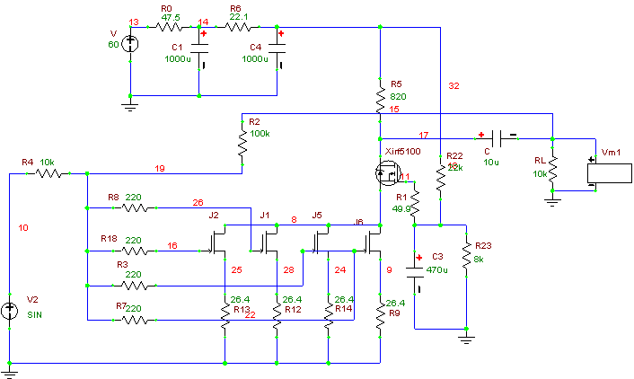
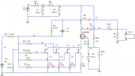
Cascode BOZ preamp:

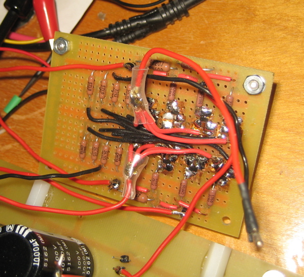
BOZ adapter board:
The voltage at the gate of the MOSFETs was 15 volts at most when I started this up. So about 12 volts across the JFETs ... not enough to hurt anything.
It's a mystery to me why this has happened twice. And I found no shorts or other problems with the circuit.
I mean I think it's more likely that the JFETs would be blown when I was measuring Idss and checking the bias currents. Any thoughts?
After this last failure I put a 9 volt battery across the drain of the JFETs of one channel and measured ~15mA current draw from every JFET. It should be around 9.0mA, which I also tested independently. In hindsight I wish I had tested them in the adapter board before hooking it up. The other channel is blown I think, and conducts.
Cascode BOZ preamp:
BOZ adapter board:
The voltage at the gate of the MOSFETs was 15 volts at most when I started this up. So about 12 volts across the JFETs ... not enough to hurt anything.
It's a mystery to me why this has happened twice. And I found no shorts or other problems with the circuit.
I mean I think it's more likely that the JFETs would be blown when I was measuring Idss and checking the bias currents. Any thoughts?
Attachments

I remember reading that Magura encountered a similar problem when he attempted to pair up LU1014D power jfets. They don't share the current evenly, I believe he said. Perhaps low value Drain resistors above the jfets would help? I'll check my sim...
Edit: In the sim I added 10 ohm drain resistors above the jfets with very little change in the performance specs... perhaps it's worth experimenting?
Edit: In the sim I added 10 ohm drain resistors above the jfets with very little change in the performance specs... perhaps it's worth experimenting?
Last edited:
Offhand, you do have the Source of one JFET attached to
the Gate of another, but most likely that is a schematic
error.
Opps ... forgot about that. Yeah, it was a schematic error ... I fixed that after taking that snapshot of the circuit awhile back.
charpenter said:I simmed your circuit with J310s for kicks and discovered that they were very unhappy in this particular configuration, which of course leads me to wonder if your jfets are encountering a similar fate.
Thanks much, for doing all the sims. I actually modeled this circuit in spice but used the LSK170C JFET model. I don't have a spice model for the BF862 either, I haven't found one yet but I may look more for one if they are out there?
I know the BF862 has significantly higher transconductance but I planned on using a bit more feedback to compensate a bit, so the gain is not to high.
I planned on using slightly higher source resistors on the JFETs but forgot. Still, they should only be pulling 9mA, which is close to the 8.6 mA in the sim and should still be biased okay.
Right now they pull 15mA and drop too much voltage across the load resistor of the MOSFET. But the do pull current equally. Which is strange that they would if they were damaged???
I may try this again, maybe with a small drain resistors on each JFET and also slightly larger degeneration resistors. I'll be sure to test the board before hooking it up.
When you say the J310 is unhappy, do you mean it didn't perform well? Didn't bias properly?
....Right now they pull 15mA ...
The Vgs of your JFETs got positive (gates got higher potential than sources).
The possible causes:
- the output coupling cap is leaking;
- you don't have a resistor (100k - 1Meg) from the point where all the gates meet to ground;
- you connected somethnig a wrong way.
I don't have a spice model for the BF862 either, I haven't found one yet but I may look more for one if they are out there?
Anthing wrong with the manufacturers, NXT, model
") ?
?.model BF862 NJF(Beta=47.800E-3 Betatce=-.5 Rd=.8 Rs=7.5000 Lambda=37.300E-3 Vto=-.57093
+ Vtotc=-2.0000E-3 Is=424.60E-12 Isr=2.995p N=1 Nr=2 Xti=3 Alpha=-1.0000E-3
+ Vk=59.97 Cgd=7.4002E-12 M=.6015 Pb=.5 Fc=.5 Cgs=8.2890E-12 Kf=87.5E-18
+ Af=1)
Also you should go for ca 40ohm source-resistors if you want 8mA.
Last edited:
Thanks for input for all the input guys!
Thanks, I've been investigating the circuit more carefully, and it does appear the JFETs are toast. Just to double check I put a 9v battery across them again with input grounded and they are each pulling 18.0mA through drain and 12uA through the gate. Should be 9.1mA. And, it's highly unlikely do to electrostatic damage given that I haven't killed one yet on my test board (below).
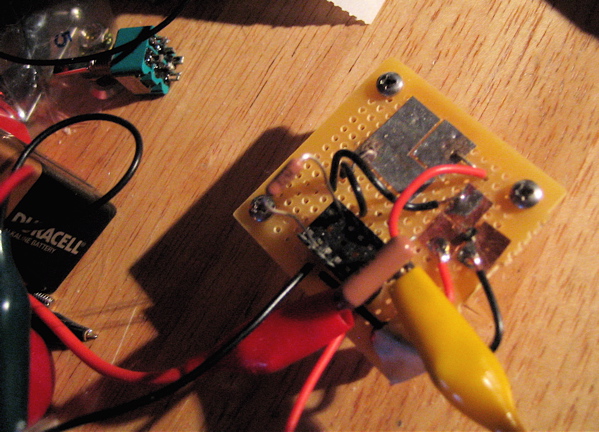
I neglected to put any load at the output when I fired it up. That may have affected stability, or maybe a transient voltage at turn on damaged the JFETs. Don't know.
I didn't look too hard I guess. Thanks for the model.
I'll start over, do some spice sims and hook up the circuit without feedback first and see if how that goes. And, I'll be sure to put, say, 20k load resistance at the output.
I used a 49.9 ohm resistance for R1 because in another cascode circuit using the IRF510, putting a larger resistance there caused a large peak at 10Mhz, I think. But, I'll do some spice sims and see what happens.
I'll put a 220 ohm resistance at the output too.
Thank You.
juma said:The Vgs of your JFETs got positive (gates got higher potential than sources).
The possible causes:
- the output coupling cap is leaking;
- you don't have a resistor (100k - 1Meg) from the point where all the gates meet to ground;
- you connected somethnig a wrong way.
Thanks, I've been investigating the circuit more carefully, and it does appear the JFETs are toast. Just to double check I put a 9v battery across them again with input grounded and they are each pulling 18.0mA through drain and 12uA through the gate. Should be 9.1mA. And, it's highly unlikely do to electrostatic damage given that I haven't killed one yet on my test board (below).
I neglected to put any load at the output when I fired it up. That may have affected stability, or maybe a transient voltage at turn on damaged the JFETs. Don't know.
revintage said:Anthing wrong with the manufacturers, NXT, model?
I didn't look too hard I guess.
Thanks for the model.Nelson Pass said:There's a mistake somewhere, and the JFETs are croaking
either from overheating or more likely high voltage.
I bet oscillation, if you don't have a scope.
You don't have a resistor in series with the output, and the
value of R1 might be too low.
I'll start over, do some spice sims and hook up the circuit without feedback first and see if how that goes. And, I'll be sure to put, say, 20k load resistance at the output.
I used a 49.9 ohm resistance for R1 because in another cascode circuit using the IRF510, putting a larger resistance there caused a large peak at 10Mhz, I think. But, I'll do some spice sims and see what happens.
I'll put a 220 ohm resistance at the output too.
Thank You.
Attachments
Last edited:
I neglected to put any load at the output when I fired it up.
But I suppose you had the 10k from output to ground connected. Otherwise this might be the cause as it is also the ground-reference for the jfet gates.
But I suppose you had the 10k from output to ground connected. Otherwise this might be the cause as it is also the ground-reference for the jfet gates.
Which begs the question: if you remove the feedback loop, will you provide another ground reference for the jfet gates?
But I suppose you had the 10k from output to ground connected. Otherwise this might be the cause as it is also the ground-reference for the jfet gates.
I had the 10k at the input grounded, but I didn't have the 10k ohm load at the output. So, I agree that this is likely the cause of the problem.
I see what you mean about that being the ground reference for the JFETs.
I'll add that 470k resistor while I'm at it.
I´d say the output resistor wether it is 10k or some other value is absolutely necessary, but not for stability. This to still have a ground-reference for the JFET gates in case you remove the source. But as I suggested before you could also add a resistor directly from the JFETs gate to ground to get this.
.Nelson Pass said:The circuit should not require an output load for stability
Okay, good to know!!! I didn't think so at first either (hence no resistor), but not sure and I'm kind of stumped here.
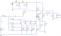
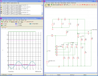
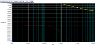
Here's the circuit schematic again but simmed with the bf862 JFET model. I added a small cap to get rid of a response peak at 1MHz. I added the 220 gate stopper to the MOSFET, which had no affect on the response in this circuit.
Here's the simmed high frequency open loop response and shows almost 20 degrees of phase margin. That's not really very good though is it?
If this all looks okay, I'll go order some more JFETs.
Attachments
- Status
- This old topic is closed. If you want to reopen this topic, contact a moderator using the "Report Post" button.
- Home
- Amplifiers
- Pass Labs
- Cascode BOZ