Okay, I guess I got phase margin wrong too.  I was quoting the margin where the open loop gain equaled 1 (0dB) and the phase margin is the difference between the phase and 180 degrees phase shift at the frequency where the closed loop gain and open loop gain are the same.
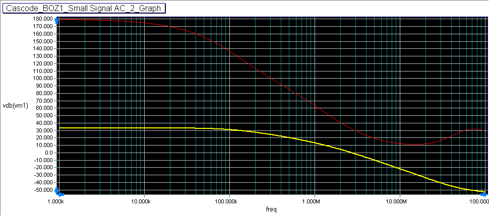
This preamp has a closed loop gain of 18dB and at the open loop gain is 18dB at 3MHz. The phase margin is 360 deg - 330 deg, that is 30 degrees.
Phase margin - Wikipedia, the free encyclopedia
And wiki says it should be 35 deg. But since this isn't a power amp driving a capacitative load, 30 deg should be okay I think.
I was quoting the margin where the open loop gain equaled 1 (0dB) and the phase margin is the difference between the phase and 180 degrees phase shift at the frequency where the closed loop gain and open loop gain are the same. This preamp has a closed loop gain of 18dB and at the open loop gain is 18dB at 3MHz. The phase margin is 360 deg - 330 deg, that is 30 degrees.
Phase margin - Wikipedia, the free encyclopedia
And wiki says it should be 35 deg. But since this isn't a power amp driving a capacitative load, 30 deg should be okay I think.
Here's the open loop response when using the LSK170C JFETs and it has almost 80 degrees phase margin. I get slightly better simulated performance with the LSK170C also, but the difference is very slight and probably doesn't mean anything in the real world. But it looks like the more stable of the two, in this circuit anyway. I've used the LSK170C in my last preamp and it sounds really good, so I may stick with those if I can get my hands on some more.
Is that like the feedback Pass used in his F5?
I usually rely on degeneration for feedback--think I'll stick with it as it seems to work fine for me.
Is that like the feedback Pass used in his F5?
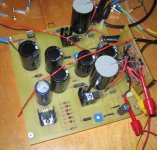
Attachments
Last edited:
Looks nice Carpenter!
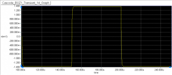
I made some modifications to my circuit to increase the phase margin using the bf862, now it is just above 50 degrees. So, I hope this works as good as the sim, since I'd like use that transistor. Any opinions about transistor matching in a circuit like this? I don't think it's really necessary, as long as they are reasonably close, but if there is a benefit I'll buy enough to match them.

Open loop response.

10 KHz square wave.

I made some modifications to my circuit to increase the phase margin using the bf862, now it is just above 50 degrees. So, I hope this works as good as the sim, since I'd like use that transistor. Any opinions about transistor matching in a circuit like this? I don't think it's really necessary, as long as they are reasonably close, but if there is a benefit I'll buy enough to match them.
Open loop response.
10 KHz square wave.
Attachments
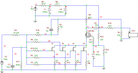
Well, I found the real problem with my circuit. I had all the gates on one channel wired to the sources and the gates on the other channel wired to the drains. Could that cause a problem??? 
I just had the 220 ohm resistors lined up wrong on the generic PCB, and I just never thought about that possibility, and never checked that out. But while checking for continuity of the JFET mounting pads, I found the shorts.
Got to check everything!!! Oh, well, at least the preamp will be more stable now.
Good luck with the next attempt.
I'll need it.
It's been awhile since I last posted, but I got distracted with a sub crossover I had to finish. Needed more bass.
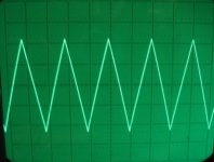
Anyway, I got this thing working! But, not without some excitement. When I first hooked up everything, after doing the modifications, it still had problems. And upon inspection I found the MOSFETs (same ones I used last time) were IRF9510 P-Channels, not the IRF510. Fortunately, the JFETs survived. And I pulled them out and put in the IRF510s. Crazy!

1kHz triangle, open loop -

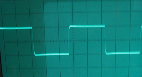
1kHz square, open loop -
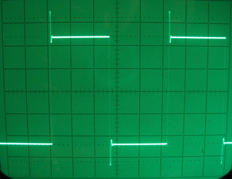
Got some ringing, and remembered I forgot to increase the gate stopper resistance like Nelson recommended.
Anyway, I got this thing working! But, not without some excitement. When I first hooked up everything, after doing the modifications, it still had problems. And upon inspection I found the MOSFETs (same ones I used last time) were IRF9510 P-Channels, not the IRF510. Fortunately, the JFETs survived. And I pulled them out and put in the IRF510s. Crazy!
1kHz triangle, open loop -
1kHz square, open loop -
Got some ringing, and remembered I forgot to increase the gate stopper resistance like Nelson recommended.
Attachments
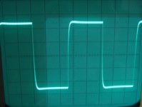
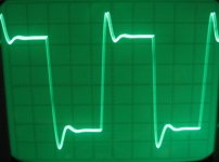
I increased the gate stopper R1 to 240 ohms, which took care of the ringing. Thanks Nelson!

Then I applied feedback -
Works! So, now got to find a box to put it in. I'll probably just hook it up to the output of a passive preamp I have for now instead of going all out. Makes it easier to experiment with different circuits and evaluate.
I'll given listening impressions when I get that far.
Then I applied feedback -
Works! So, now got to find a box to put it in. I'll probably just hook it up to the output of a passive preamp I have for now instead of going all out. Makes it easier to experiment with different circuits and evaluate.
I'll given listening impressions when I get that far.
Attachments

Last edited:
Any ideas on where I can get some inexpensive project boxes? They need to be 3.5 inches high. Right now I'm thinking Hammond but welcome other suggestions.
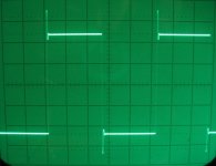
And I neglected to mention that the second square wave responses are the open loop and closed loop at 10kHz, not 1kHz. For 1kHz those responses wouldn't be so good, I think. Here's what 10kHz open loop looked like before increasing the value of R1.
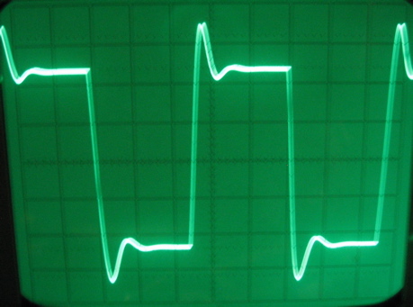
And I neglected to mention that the second square wave responses are the open loop and closed loop at 10kHz, not 1kHz. For 1kHz those responses wouldn't be so good, I think. Here's what 10kHz open loop looked like before increasing the value of R1.
Attachments
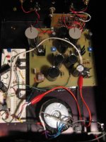
It's been awhile, but I finally put this in a test box to see how it sounds. Only problem is I found it's noisy. Even though the power supply is real quiet, on the other side of the drain resistor is noise (MOSFET drain) it is noisy. It's at -81dBV.
I bread boarded a shunt regulator to make it even quieter ( -122 dBV ) right at the limit of what I can measure.

I bread boarded a shunt regulator to make it even quieter ( -122 dBV ) right at the limit of what I can measure.
Attachments
- Status
- This old topic is closed. If you want to reopen this topic, contact a moderator using the "Report Post" button.
- Home
- Amplifiers
- Pass Labs
- Cascode BOZ