Its not only they shift the arm cart resonance to a more "optimum range". The "ballast" plates are probably having a damping effect on the cartridge mounting end also. Anyway since you are a Pearl user don't forget to let people know how it went for you here in the end.
Hello, Mr dB. I have an OL counterweight and a structural upgrade. I don't know if it's any heavier, as I never had a stock one to compare. Yes, it's said that 103R prefers heavier arms. Although, a little note, it's compliance is measured at 100Hz and there are many happy users with RB300 tonearms. It gives me a hint that it still can be a good match.
I don't know how it works with the Origin Live weight, but with a DL103R on a standard RB300 with the standard sintered tungsten weight, to balance the cartridge you'll have to pull the weight out to where the first O-ring is about to pop off the end. The optional Rega heavy counterweight is more than sufficient though.
Of course. I'll let you know. Although, I'm taking my time with a TT build so it won't happen that soon. In the meantime, here are my voltages to compare.
So where can we see this TT build project?

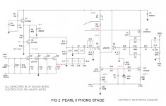
Try 1K trimmer connected as rheostat instead of R28 and trim for 1.5V across R6 first. Then see again with P1. Your LED is higher than 1.7V Vf most probably.
Q3 is squashed for Vce in your annotated schematic measurements. Try 15-22 Ohm R21-24 to give it breath. Your input quartet IDSS is probably higher than in the original.
Should I try that too?
Not the trimmer as you can make yours show near 0V at that node as it works now. About input stage higher R21-R24 resistors is up to you to test if you can hear any better. It works at 26mA and lower Vds now instead of 20mA as drawn, but it works. You should restore to 10K R10 first if trying with more R21-24 value.
So where can we see this TT build project?
It looks quite ugly in the current state. Nothing too fancy. It's a Lenco idler drive mechanism on an improved top plate and in a still to be moulded resin / bentonite plinth. All that in pair with my RB300. Scrappy testing proved quite promising.
Last edited:
I swapped out a 1k pot for R28 and attempted to trim the voltage across R6 to 1.5 v. When I first turned on (Pot at R28 ~ 500 ohm) voltage was around 3.0 v and I was not able to lower it to 1.5 v - only about 2.0 v. I put a second DMM on the junction between R16 and R17 and the voltage was very high around 18 v. By trimming the Pots at both R28 and P1 and observing the 2 DMMs, I was able to get 1.5 v across R6 and around 0 at the R16/R17 junction - although it was varying quite a bit 200 ms at the junction. I did not spend a lot of time observing.
I let it burn in for a few hours and went back to measure again. Voltage across R6 was still 1.5 v, but the voltage at the R16/R17 junction point had moved up to around 1.2 V. I observed for several minutes and found the voltage readings varied a lot - 125 mv to +1.3 V - very unstable. It would stabilize at a point for 10 seconds that vary up down for another 10 seconds, then stabilize, vary, etc. Voltage at R6 would stay stable and only change if I adjusted either Pot.
I connected the TT and amp and once again got very load buzz at moderate volume - brutal noise that says something is really wrong!
Any other ideas for next steps?
Here are my measurements against Wayne's.
Start at the beginning, the voltage around Q3 is wrong, once sorted move on to the hum problem.
In Wayne's circuit the JFET's are drawing 20mA, bnorrish your circuit is drawing 28mA, adjust the value of R9 to 330R or 360R to compensate 10V/0.28mA=~360R.
Seberia has the same problem.
Do you have hum at the collector of Q3?
I swapped out a 1k pot for R28 and attempted to trim the voltage across R6 to 1.5 v. When I first turned on (Pot at R28 ~ 500 ohm) voltage was around 3.0 v and I was not able to lower it to 1.5 v - only about 2.0 v. I put a second DMM on the junction between R16 and R17 and the voltage was very high around 18 v. By trimming the Pots at both R28 and P1 and observing the 2 DMMs, I was able to get 1.5 v across R6 and around 0 at the R16/R17 junction - although it was varying quite a bit 200 ms at the junction. I did not spend a lot of time observing.
I let it burn in for a few hours and went back to measure again. Voltage across R6 was still 1.5 v, but the voltage at the R16/R17 junction point had moved up to around 1.2 V. I observed for several minutes and found the voltage readings varied a lot - 125 mv to +1.3 V - very unstable. It would stabilize at a point for 10 seconds that vary up down for another 10 seconds, then stabilize, vary, etc. Voltage at R6 would stay stable and only change if I adjusted either Pot.
I connected the TT and amp and once again got very load buzz at moderate volume - brutal noise that says something is really wrong!
Any other ideas for next steps?
Are the ground prongs of the XLR jacks grounded to the cases? The ground floats on mine.
Start at the beginning, the voltage around Q3 is wrong, once sorted move on to the hum problem.
In Wayne's circuit the JFET's are drawing 20mA, bnorrish your circuit is drawing 28mA, adjust the value of R9 to 330R or 360R to compensate 10V/0.28mA=~360R.
Seberia has the same problem.
Do you have hum at the collector of Q3?
Hum would be too subtle a term! Keep in mind I have a working channel with very similar voltages on the front end. I may go back and tune after I fix this channel. No music very load buzz
How would I check hum at collector of Q3? I do not have a scope, yet.
Are the ground prongs of the XLR jacks grounded to the cases? The ground floats on mine.
On the power supply side, I have it grounded per Wayne's PSU diagram. Board side is on the bench, floating. The working channel is quiet.
adjust the value of R9 to 330R or 360R to compensate 10V/0.28mA=~360R.
That will drop the stage's gain. R21-24 higher is the right way IMO.
Hum would be too subtle a term!
So it can get the voltage down but it shows instability and a terrible hum...can be oscillation I am afraid. Without a scope is difficult to know. In that case I would start changing the semis around that stage starting with the ZVP and rechecking with each substitution.
P.S. Is there any history with C9 value creating loop feedback instability and needing experimentation, or incidents of putting there a bit wrong value and setting off?
Yes. I had put a jumper on Cx by mistake - it is now open. I replaced ALL the transistors except the 2ks170s after I opened. Replace Q4 and Q5?
Ooops. So it was oscillation. Do a test at this point to see what happens first.
This all happened before the steps you suggested, a few days ago. I can test again but nothing has changed.
- Home
- Amplifiers
- Pass Labs
- Pearl Two