How critical is the Wattage or VA ? ...... Am I creating too many problems
using this .... ?
MULTICOMP|MCFE050/25|TRANSFORMER, 50VA, 2 X 25V | Farnell United Kingdom
or this .... BLOCK|RK40/22|TRANSFORMER, 40VA, 2 X 22V | Farnell United Kingdom
Also available from these guys for a couple of quid less.They seem to be tied in with Farnell so don't get the price difference. Farnell are good and quick though having been woken up at 7.30 in the morning by there delivery people even when some items have had to come from one of there european sites.
MULTICOMP|MCFE050/25|TRANSFORMER ENCAPS. 50VA 2X25V | CPC
that should look wonderful with silver wire surrounded by mundorf M-lytic caps ......
I think I'll just leave this thread for the chosen ones.... sorry for wasting your time !
I think I'll just leave this thread for the chosen ones.... sorry for wasting your time !
Pearl Problem ?
Gents ,
So , now I need some of the genius lurking . I have a problem with one of the boards . I keep blowing fuses .
Voltage from PSU is solid and stable @ 40.2 VDC on both + & - . There was
little smell when I first turned it on . The LED dimmed never to return .
The fuse is 250mA . I have had the working board running for about 3 hours with no problems . I have taken photos , visual inspection proved sound . Solder joints are solid with no shorts .
Short of dismantling the board are there any suggestions on how I may find the fault . ?
thank you , Rich
Ok ..... it would help if I didn't have the + and - the wrong way round . At least that explains the 8 fuses in the bin !
Now I have nothing , but distortion and the occasional pop .... Test speakers at low volume . Its the same out of both channels ....🙁 ????? any ideas guys ?
Cheers , Rich
Now I have nothing , but distortion and the occasional pop .... Test speakers at low volume . Its the same out of both channels ....🙁 ????? any ideas guys ?
Cheers , Rich
At least, you should change the on-board regulators and the led for new ones 🙂
If no improvement, go on with the bipolars replacement ... at least I hope the precious jfet are still alive, but maybe not.
You could also have fried some resistors. Your mileage may vary.
Best,
nAr
If no improvement, go on with the bipolars replacement ... at least I hope the precious jfet are still alive, but maybe not.
You could also have fried some resistors. Your mileage may vary.
Best,
nAr
Last edited:
Rich build yourself a light bulb tester if you havent already done so it saves a fortune in blown fuses and generally stops anything from cooking. Won't tell you where the problem is but lets you know there is a problem before damage is done.
Won't tell you where the problem is but lets you know there is a problem before damage is done.
Yes, but in his case it's better to know where the problem is

Bulb would be for another time ... good idea 😎
Do I need to change regs on both boards or just the one blowing the fuse ... ?
I changed the ones on the bad board and no change - still got the same distortion .... I have just ordered new caps 22uf and 3300uf ... I'll call pass this afternoon and order new j fets.
Rich
I changed the ones on the bad board and no change - still got the same distortion .... I have just ordered new caps 22uf and 3300uf ... I'll call pass this afternoon and order new j fets.
Rich
I had it working last week ,but not with proper PSU . I turned it off and got some pretty frightening cracks through the speakers ....
I have not used it since .... When I say working board .. I mean it doesn't blow a fuse ...
I got the .0033 uF suggested ,put it in and lost another fuse . Now back to the 4x 1000pf I made up and fuse is ok .
Just changed cables ... thats not it . The distortion is consistent through L&R
I get sound ,but nothing I'd want to listen to, except maybe as an alternative to water-boarding .
Trying to laugh about it ,but it aint easy as the cost starts to eat into other things ! B1 is a thing of fantasy for the foreseeable future !
Wounded , but not dead yet , Rich
Ok ..... I just spoke to Wayne ... I need 24 VDC + and - after the onboard Reg .... Where do I measure from please ?
Jfets are not a problem to replace , but he doubts "Death by Richard " was successful !
Which is the 0 v leg and which is the 24 V leg ?
Rich
Jfets are not a problem to replace , but he doubts "Death by Richard " was successful !
Which is the 0 v leg and which is the 24 V leg ?
Rich
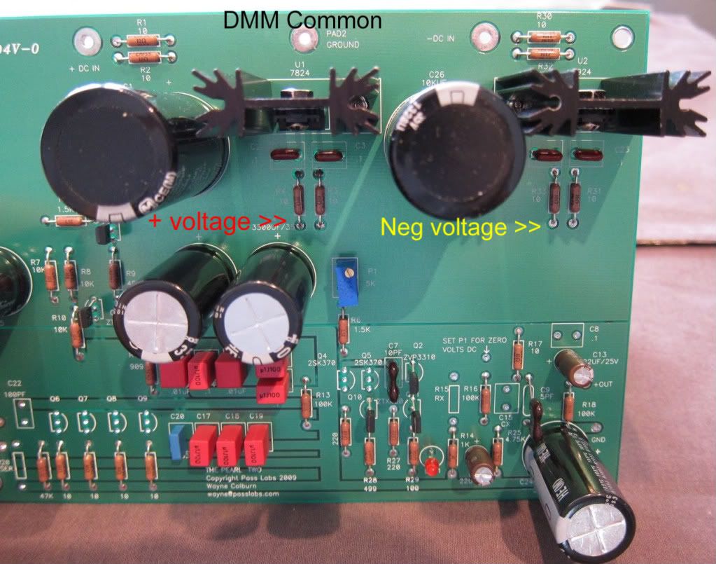
Use the "Ground" pad for the common (black) lead on your multimeter.
Measure (+) volts on the bottom leg (further away from the heatsink) of R3 or R4
Measure (-) volts on the bottom leg (Again, further away from the heatsink) of R31 or R33
I will take a photo and make some notes on it.
Measure (+) volts on the bottom leg (further away from the heatsink) of R3 or R4
Measure (-) volts on the bottom leg (Again, further away from the heatsink) of R31 or R33
I will take a photo and make some notes on it.
thanks 6 ,
that checks out OK , within 1/2 a vdc . I have the correct polarity too !
next ? any ideas ? BTW , Wayne said just to email him if needed .
Nice man , didn't make me feel like joker for a mili - second
Rich
that checks out OK , within 1/2 a vdc . I have the correct polarity too !
next ? any ideas ? BTW , Wayne said just to email him if needed .
Nice man , didn't make me feel like joker for a mili - second
Rich
That's wonderful news!
Start looking for backwards components. Then start measuring resistors one at a time.
Also, somewhere on this thread there is a schematic with the proper voltages drawn in. Check those.
Yes, Wayne is a wonderfully nice guy. I had a chance to sit down with him a pick his brain about the Pearl 2 at Burning Amp, I walked away more knowledgable and with a few insights into the project. A great guy through and through.
Lets talk p1 5k multi .... checking it it reads 17.28 .... needs to be 0 ? pad G to pin ?
I'll look for the schematic too !
I don't remember seeing any on Wayne's original.
R
I'll look for the schematic too !
I don't remember seeing any on Wayne's original.
R
- Home
- Amplifiers
- Pass Labs
- Pearl Two