Milosz,
Thanks for your reply, information, you stated it much bettter than I. I see at as Iron/steel concentrates the M field, (leakage flux) thus you can direct/concentrate it to some degree.
This is how they find Fe in the ground, by measuring the earths Mag field, concentration of flux density using a magnetometer. Check it out, a cesium beam mag using the lamor principle.
http://scintrexltd.com/dat/content/CS-3.pdf
There has to be a good reason why hi quality transformers are shielded with steel.
I have a small hand held device that picks up these fields. Its design use was to determine which polarity results is less field. (I dont know if that really helps, but the field is stronger one way than the other) and I can detect fields easily no matter what the case is made of. Basically, you can make your case out of whatever, if its close it will hum.
Russellc
Russellc
Is this kind of resistor appropriate for R21-24 positions?
YR1B20RCC - TE CONNECTIVITY / NEOHM - RESISTOR, METAL FILM, 20R, 250MW | Farnell United Kingdom
I'll go for 20 ohms value to see what it gives on input jfets. At the moment I've got around 69-70mV across each.
YR1B20RCC - TE CONNECTIVITY / NEOHM - RESISTOR, METAL FILM, 20R, 250MW | Farnell United Kingdom
I'll go for 20 ohms value to see what it gives on input jfets. At the moment I've got around 69-70mV across each.
My Pearl 2 build has been up and running and making sweet music for the last two weeks and sounds great!
Trouble is I can now hear all the faults in my humble Systemdek. Upgraditis has struck me.
Thanks to Jim (6L6) for the great build guide and all the great minds here for the wise posts.
Right, now for an Aleph J and a DCB1.
Trouble is I can now hear all the faults in my humble Systemdek. Upgraditis has struck me.
Thanks to Jim (6L6) for the great build guide and all the great minds here for the wise posts.
Right, now for an Aleph J and a DCB1.
")
Hi everyone,
first of all happy new year to all Pearl 2 enthusiasts!
I finished my Pass Pearl 2 about a year ago but due to personal reasons I did not really have the time to test and enjoy it...
Now I am back on track and have time to fiddle around with the Pearl 2 - and
I am having some weird sound phenomina:
Whenever I listen to records with great dynamic peaks or so I get distortion and clipping with my Pearl 2. I have changed the pickups from Benz Glider (heavy clipping) to Denon DL 103 (less clipping but still disturbing) and I have also tried the "Zobel" network as Wayne described in another post (resistor and capacitor in series bridging the RCA input jacks) but no luck with this one.
Does any of you have encounterd similar problems? Might it be that the JFETs are gone or damaged? What can this be?
I don't hear hiss or hum from the stage, everything else is fine but the distortions are really irritating.
Thanks for any hints!
Best regards
Michael
Both the Glider and the Denon should not put out enough voltage to drive the Pearl into clipping (not by a long shot). So I would first make sure the cartridges are set up right (VTF, anti skating etc). Then rule out the possibility of bad pressings. And finally check the values of some components in the Pearl. For instance the resistors that define the gain (should be between 300R and 1K) and the resistor that determines input impedance. If none of this solves the case I would indeed check the FETs and transistors.
Hi everyone,
thanks for the answers so far.
Well, I can rule out, it's the pickups being badly adjusted, cos they do well on my other whest phono-stage, so there is definitely something wrong with the Pearl 2.
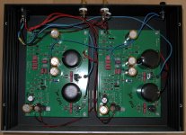
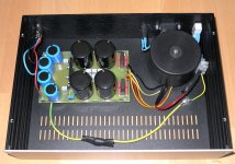
Attached please find some photos of the Pearl 2 phono stage and my PSU.
@6L6 - can you see something in there? did I make a mistake somewhere?
Thanks and best regards
Michael
thanks for the answers so far.
Well, I can rule out, it's the pickups being badly adjusted, cos they do well on my other whest phono-stage, so there is definitely something wrong with the Pearl 2.
Attached please find some photos of the Pearl 2 phono stage and my PSU.
@6L6 - can you see something in there? did I make a mistake somewhere?
Thanks and best regards
Michael
Attachments
Hi everyone,
thanks 6L6 - I am back with some voltages:
Honestly I have never managed to get exactly 0V at the test pad, I am having heavy drifts...right now, I am getting 2,2 V for the left channel and -2,5 V for the right. The voltage moves away when I even get close with a scredriver to pot P1. What to do?
I measured quite a few voltages according to Waynes plan, all seem to be ok - but the only thing that really stroke me was the deviation in voltages at the drain of Q2 (the pin right next to Q11) against ground - I am measuring -0,4 V left and -5.7 V right at Q2, this is probably not the way it should be - do you have any figures for reference, please?
John mentioned in his post that apparently there was something wrong with this mosfet, so should I replace them both?
What's the story with C7 bridging Q2? Is it worth completelly removing it?
BTW: C22 at the input has 100pF as suggested, for R20 I used a 900 Ohm resistor plus R19 with 47 KOhm.
Zobel is removed, it didn't help anyway.
Thanks and best regards
Michael
but the only thing that really stroke me was the deviation in voltages at the drain of Q2 (the pin right next to Q11) against ground - I am measuring -0,4 V left and -5.7 V right at Q2, this is probably not the way it should be - do you have any figures for reference, please?
The voltages around Q2 are on the voltage map, however as they are not printed right on the mosfet symbol you have to search a little...
The Source is attached to the +rail, the gate is attached to the bottom of P1, which should be adjusted to give 21V, and the Drain is to the junction of R16 and R17, where everything can hopefully be adjusted to give zero volts DC.
S +24
G +21
D 0
Replace the ZVP. It is very common when building the Pearl 2 to have to do this. Also remove C7.
Thanks guys for help - I just love this forum!
@6L6: Ok, so I will remove Q2 and have it replaced with another one ZVP3310.
Are you saying in normal operation mode one would get 0 V at the drain of Q2, right? Well I do get +23 V at the source but apparently there is something wrong in the mosfet device, so I'll replace it...
@Salas: Ok, so it should be exactly 10.1 V and 9.4 V - according to the plan, right? What about Q1 - ist that not so critical?
What about the JFETs? Might they have to do with the clipping as well?
Thanks and best regards
Michael
What about the JFETs? Might they have to do with the clipping as well?
Did you get the JFETs with the PCB? Then they are genuine.
Please don't assume anything is wrong with the front end -- it's voltages are essentially correct, while there is an issue with the output stage.
Get everything to measure correctly first. If there is still a sonic issue, then start thinking about other possible problems.
I think that a fresh 3310 will solve your issues.
- Home
- Amplifiers
- Pass Labs
- Pearl Two