Has the pass store just doubled the price on the boards? :-(
Nope. I just talked with them. Its 200 for 2 boards and 2 x 6 matched JFETS.
Confusing though eh.. I thought the same.
Phase Inversion Switch
found that looking for means to invert phase... not sure if its quite right. would be interested in critical opinions of others. I suspect (without knowing) that impedance issues might arise?
i might forget it all together and, as advised previously, deal with it down the road if i can. Thought id share the info incase others find themselves pondering the same ideas
Hi folks,
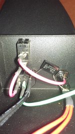
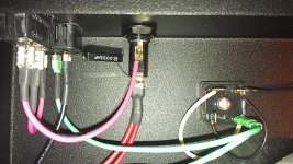
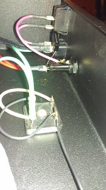
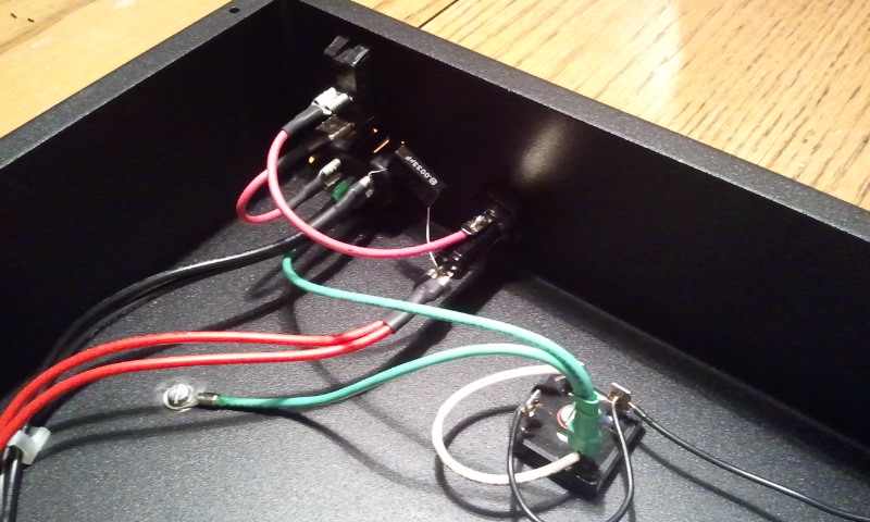
I have what is probably a dumb question, most appropriate for budwiser, as it is his picture, but I am guessing many can answer it. The link is to a picture of budwiser's power supply, which I am trying to copy. This is my introduction to electronics projects.
http://www.diyaudio.com/forums/atta...d1329711222-pearl-two-2012-02-19-22.59.04.jpg
My question: in Wayne's schematic, he runs the hot line from the wall into the fuse, than to the transformer. It looks like in this photo the neutral is running to the fuse. I assume I am missing something obvious, but would appreciate it if someone would tell me what. I am a trial and error kind of guy, but not when it involves 120 volts. Thanks!
I've received today my Pearl Two PCB's and fets from the Passdiy store.
After reading through this thread, now time for some questions")
I'm thinking to feed them with Salas shunt regs (one Mezmerize board per channel). Another Mezmerize, fully populated, will be my DCB1 line preamplifier.
1) Should I fit the regulators inside the RIAA chassis, leaving only the trafo outside, or better move the whole psu in a separate enclosure, 3ft away?
2) When using the regulated psu I know that the 7x24 regulators have to be removed.
Is this the only modification ? Other thingies to be left out ? Where in the board I have to apply the voltage coming from the psu ?
3) Without the Pearl's regulators, I understand that the shunted PSU has to provide 24V 100mA to the board, so I need to set the Salas reg for 24V, 200mA.
Any good in "hot-rodding" the shunt, let's say 400mA instead of 200 ?
4)The trafo's output, for Salas' instructions, should be (24V+7V)/1.41=22V.
Is a -24/0/+24V 150VA toroidal good for this ? (maybe I move this question to the shunt's thread)
Very basic questions, I know, but I don't want to be wrong when filling my BOM
Thanks a lot! cheers. Carlo.
After reading through this thread, now time for some questions
I'm thinking to feed them with Salas shunt regs (one Mezmerize board per channel). Another Mezmerize, fully populated, will be my DCB1 line preamplifier.
1) Should I fit the regulators inside the RIAA chassis, leaving only the trafo outside, or better move the whole psu in a separate enclosure, 3ft away?
2) When using the regulated psu I know that the 7x24 regulators have to be removed.
Is this the only modification ? Other thingies to be left out ? Where in the board I have to apply the voltage coming from the psu ?
3) Without the Pearl's regulators, I understand that the shunted PSU has to provide 24V 100mA to the board, so I need to set the Salas reg for 24V, 200mA.
Any good in "hot-rodding" the shunt, let's say 400mA instead of 200 ?
4)The trafo's output, for Salas' instructions, should be (24V+7V)/1.41=22V.
Is a -24/0/+24V 150VA toroidal good for this ? (maybe I move this question to the shunt's thread)
Very basic questions, I know, but I don't want to be wrong when filling my BOM
Thanks a lot! cheers. Carlo.
1) Yes, the regulators need to be as close to the load as possible. Place the transformer in the separate enclosure.
2)If you can't look at the schematic and determine what pieces of the regulator need to be omitted, and where the shunts need to be attached, I strongly suggest you build the Pearl in it's 'stock' (normal) configuration first, get the circuit working first (almost everybody has some issue in the beginning) and only when it's working perfectly, then use the shunt regulators.
3) The powersupply needs to make +/-24v not just +24v. Shunt regulators need to be set for the load - no more, no less.
4) Yes, a 24v+24v transformer will be fine. 150VA is a bit big, but that won't hurt anything.
Glad to hear you are building a Pearl 2! It's a wonderful phonostage, I'm sure you will be happy with it.
6L6, I disagree -
Building both supplies seems a waste of parts potentially.
Here is my modded schematic, this is what my P2 boards look like without the built in regulators.
I would mount the Reg in the same chassis as P2 boards, but keep trafo in another box, with DC rectification happening near the Trafo, a 1000uf cap, and a bleeder resistor across the 1000uf cap in trafo box.
You guys are great! Just a few minutes and you gave me a lot of info, and a full schematic too
My idea is then to place inside the same chassis the two regulator boards (Mezmerize portions) side to side, and the two RIAA boards one on top of the other, to save space and keep the in/out cabling shorter.
Without the 7x24 regulators I guess that the lower board won't generate any warmth (or just a little), so the upper one is not affected. A hifi2000 chassis with a perforated top will host the four boards nicely.
Thanks!
You guys are great! Just a few minutes and you gave me a lot of info, and a full schematic too
My idea is then to place inside the same chassis the two regulator boards (Mezmerize portions) side to side, and the two RIAA boards one on top of the other, to save space and keep the in/out cabling shorter.
Without the 7x24 regulators I guess that the lower board won't generate any warmth (or just a little), so the upper one is not affected. A hifi2000 chassis with a perforated top will host the four boards nicely.
Thanks!
If you stack the boards on top of eachother it will not be possible to set P1 without taking out the top board. But then again, that is not something you will be doing everyday.
- Home
- Amplifiers
- Pass Labs
- Pearl Two