Good incentive to finish my Pearl 2. I am afraid to add up what a Pearl 2 costs - maybe $550-600. Still need to save some money for a good cartridge - cannot DIY one of those. Any suggestions for under $500 phono cartridges suited for a Pearl 2? How would a Dynavector 10x5 work with the Pearl 2?
I am afraid to add up what a Pearl 2 costs - maybe $550-600.
That's about what I have in mine. It's a very expensive project for DIY.
But it is completely worth it.

As the Dynavector 10x series has always been incredibly high on the price/performance scale, I'm sure it will be incredible. It's a fantastic cartridge.How would a Dynavector 10x5 work with the Pearl 2?
Last edited:
Good incentive to finish my Pearl 2. I am afraid to add up what a Pearl 2 costs - maybe $550-600. Still need to save some money for a good cartridge - cannot DIY one of those. Any suggestions for under $500 phono cartridges suited for a Pearl 2? How would a Dynavector 10x5 work with the Pearl 2?
The Dynavector is a high-output MC.
The Dynavector is a high-output MC.
Yes it is. Is that a problem in your experience?
I have had fantastic results with HO MC carts with the Pearl 2. (Specifically Ortofon X5-MC and Denon DL-110)
The Dynavector is a high-output MC.
High-output MC seems to be a good fit with Pearl2. One person on here said he needed a step up transformer with a low-output cartridge (Denon 103) with the Pearl 2. My current rig is a Rega RP1 with a Rega Bias 2.
I bought the boards with matched FETs for $200 from Passdiy.com. The boards are very high quality - Rolls Royce of PCB boards. Also the layout is very logical - easy to follow along with schematic layout.
I got all my resistors soldered today. Taking my time, measuring each resistor, matched the values on both sides - not sure if it makes much difference. All the 1% parts are pretty close anyways.
I got all my resistors soldered today. Taking my time, measuring each resistor, matched the values on both sides - not sure if it makes much difference. All the 1% parts are pretty close anyways.
Taking my time, measuring each resistor, matched the values on both sides - not sure if it makes much difference.
I think matching parts as close as possible in the RIAA filters should help imaging. If I were to build mine again, I would spend more time matching those resistors and caps so the left and right frequency responses are as close as possible. IMO it is a very nice sounding phono stage.
Having the original boards is indeed much easier than point-to point soldering as I did (especially when you do the channels mirrored). I spent most time drawing out a layout and its connections before starting the actual soldering.
I also spent some time matching resistors and caps for the channels. Probably won't make that much of a difference, but it is part of the fun and gives you the idea of working on a real high end product. I would pay most attention to the resistors and caps of the RIAA section and the R14/R16 couple which determines the gain.
I also spent some time matching resistors and caps for the channels. Probably won't make that much of a difference, but it is part of the fun and gives you the idea of working on a real high end product. I would pay most attention to the resistors and caps of the RIAA section and the R14/R16 couple which determines the gain.
High-output MC seems to be a good fit with Pearl2. One person on here said he needed a step up transformer with a low-output cartridge (Denon 103) with the Pearl 2. My current rig is a Rega RP1 with a Rega Bias 2.
I wonder if people who need more gain for the Pearl 2 and low-output MC cartridges are using unity-gain line stages?
Completed my Pearl 2
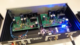
We'll after a 2 years of playing with Wayne's circuit and boards, I finally got my Pearl 2 up and operating. I had to break my leg to have enough time off work to finish this thing, but it was (almost) worth it.
Wow ! What an awesome sounding circuit. I directly compared the finished product to a brand new Pass XP-15, (with a Shelter 90X MC), and, dudes, Wayne didn't pull any punches with this one, it is CLOSE.
The XP-15 is quieter and has more gain, BUT the family resemblance is obvious, and the Pearl 2 is better than any other solid-state or tube phono preamp I have ever heard. Thank you, Wayne, for putting such a neat project in our hands, Mike Missel, my local tech, (the BEST in St. Louis), for sorting out a few problems with his distortion analyzer and years of experience that escaped me, and Toshiba for creating the 2SK170 / 370 family of JFETs which are still probably the most linear small signal semiconductors ever made.
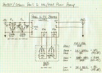
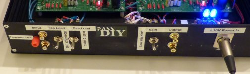
I've attached a circuit diagram and three pictures. The only changes to the circuit are removal of C7 to prevent oscillation, and the cartridge loading and variable gain circuit I added to allow for a full range of MM and MC cartridges.
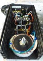
MM fans should be warned that this baby really has too much gain for MM's or MI's above 3.5 mv output....you need to turn it down with a shunt resistor across R16. In addition, a shunt resistor across R14 allows you to increase gain for low output MC's (< .2 mv, ie., Denon DL-S1 / Fidelity Research F7, etc.) For the power supply, I used a remote box, full IXYS FBE-22-0N1 fast/soft recovery bridges for both polarities, an Antek AN-0522 50VA toroidal transfomer, and a standard 3-pin XLR connector with a Canare mic cable.
We'll after a 2 years of playing with Wayne's circuit and boards, I finally got my Pearl 2 up and operating. I had to break my leg to have enough time off work to finish this thing, but it was (almost) worth it.
Wow ! What an awesome sounding circuit. I directly compared the finished product to a brand new Pass XP-15, (with a Shelter 90X MC), and, dudes, Wayne didn't pull any punches with this one, it is CLOSE.
The XP-15 is quieter and has more gain, BUT the family resemblance is obvious, and the Pearl 2 is better than any other solid-state or tube phono preamp I have ever heard. Thank you, Wayne, for putting such a neat project in our hands, Mike Missel, my local tech, (the BEST in St. Louis), for sorting out a few problems with his distortion analyzer and years of experience that escaped me, and Toshiba for creating the 2SK170 / 370 family of JFETs which are still probably the most linear small signal semiconductors ever made.
I've attached a circuit diagram and three pictures. The only changes to the circuit are removal of C7 to prevent oscillation, and the cartridge loading and variable gain circuit I added to allow for a full range of MM and MC cartridges.
MM fans should be warned that this baby really has too much gain for MM's or MI's above 3.5 mv output....you need to turn it down with a shunt resistor across R16. In addition, a shunt resistor across R14 allows you to increase gain for low output MC's (< .2 mv, ie., Denon DL-S1 / Fidelity Research F7, etc.) For the power supply, I used a remote box, full IXYS FBE-22-0N1 fast/soft recovery bridges for both polarities, an Antek AN-0522 50VA toroidal transfomer, and a standard 3-pin XLR connector with a Canare mic cable.
Attachments
We'll after a 2 years of playing with Wayne's circuit and boards, I finally got my Pearl 2 up and operating. I had to break my leg to have enough time off work to finish this thing, but it was (almost) worth it.
Wow ! What an awesome sounding circuit. I directly compared the finished product to a brand new Pass XP-15, (with a Shelter 90X MC), and, dudes, Wayne didn't pull any punches with this one, it is CLOSE.
The XP-15 is quieter and has more gain, BUT the family resemblance is obvious, and the Pearl 2 is better than any other solid-state or tube phono preamp I have ever heard. Thank you, Wayne, for putting such a neat project in our hands, Mike Missel, my local tech, (the BEST in St. Louis), for sorting out a few problems with his distortion analyzer and years of experience that escaped me, and Toshiba for creating the 2SK170 / 370 family of JFETs which are still probably the most linear small signal semiconductors ever made.
I've attached a circuit diagram and three pictures. The only changes to the circuit are removal of C7 to prevent oscillation, and the cartridge loading and variable gain circuit I added to allow for a full range of MM and MC cartridges.
MM fans should be warned that this baby really has too much gain for MM's or MI's above 3.5 mv output....you need to turn it down with a shunt resistor across R16. In addition, a shunt resistor across R14 allows you to increase gain for low output MC's (< .2 mv, ie., Denon DL-S1 / Fidelity Research F7, etc.) For the power supply, I used a remote box, full IXYS FBE-22-0N1 fast/soft recovery bridges for both polarities, an Antek AN-0522 50VA toroidal transfomer, and a standard 3-pin XLR connector with a Canare mic cable.
Fantastic work! I'm really interested in your variable gain circuit, as I have a low gain amp.
My DMM does not measure capacitance. Any other way to match caps?
You could make an RC circuit and measure the voltage change over time ...
[/QUOTE=dcbingaman;3354691]
MM fans should be warned that this baby really has too much gain for MM's or MI's above 3.5 mv output..../QUOTE]
Great build.
Right now I have a Rega Bias 2 with 6.8 mv. Is it a matter of just turning down the volume compared with the CD, Sonos or would this high-ouput cause other issues?
I will show my wife - maybe she will OK a Dynavector 10x5.
Last edited:
Pearl 2 Update
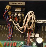
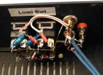
6L6 - here are some more photos of the back panel. 2PDT and 4PDT switches which have three positions (on-off-on) give you lots of possibilities for this application. In addition, unlike those 8-section dip switches, these big dudes have large contacts, and are easy to switch "blind" from the front side without pulling the thing out of your rack.
bnorrish - WRT gain control. The second stage starts to overload in the bass at about 3.5mv input according to Mike's distortion analyzer. Two ways to prevent this are to change the equalization on the bottom in the RIAA network between the first stage and the second stage, or to reduce the gain in the second stage. The open loop gain of the second stage is about 80, so there is a lot to play with here. Fortunately, if you put a switch in to shunt R16, it is easy to change the second stage gain. You can go too far with this though, Wayne warned me not to drop the overall gain lower than about 45 dB or you risk instability in the second stage. Note, the Pearl 1 had about 40 dB of gain and worked well with every MM I threw at it, but I never tried one of those hot Rega MM's.
Attachments
- Home
- Amplifiers
- Pass Labs
- Pearl Two