Sorry for my oversight, I had changed the values as indicated in my simulation - R11 to 5.6k, and additional 22 Ohm in series with C14/C10/C11.
best regards
R11 understood, for the 22 ohm additional R you put it in series with bank of C14/C11/C10; before bank of after ? I mean, at R11/R12 node or after capa bank to GND ?
Best,
nAr
Hi nAr,
the 22 ohm resistor - I put it from the gate connection to the capacitors, simply because it fitted better. For the modification , I took out the caps, and soldered them back in at the GND side with one leg looking "up", to which I connected the one end of the resistor, the other end went into the gate trace == R11/R12 node.
Maybe having the bulk of the capacitor connected to GND helps wiht noise pickup or so, I cannot think of other good reasons.....
After listening some more, I must say I more and more like the sound, detailed and relaxed. I do mostly like the sweet mids and also the good bass. The soundstaging has improved over time, but still isnt quite perfect. But then,there is a reason why say the XP25 costs so much, I guess....
best regards
This is clear thanks. Now we all wait for Wayne's advice about the modHi nAr,
the 22 ohm resistor - I put it from the gate connection to the capacitors, simply because it fitted better. For the modification , I took out the caps, and soldered them back in at the GND side with one leg looking "up", to which I connected the one end of the resistor, the other end went into the gate trace == R11/R12 node.
Maybe having the bulk of the capacitor connected to GND helps wiht noise pickup or so, I cannot think of other good reasons.....
After listening some more, I must say I more and more like the sound, detailed and relaxed. I do mostly like the sweet mids and also the good bass. The soundstaging has improved over time, but still isnt quite perfect. But then,there is a reason why say the XP25 costs so much, I guess....
best regards
")
Best,
nAr
The simulation is accurate but it's schematic doesn't match the actual circuit.
The 499 Ohms is also paralled with the cascode transistor collector.
If I understand the modification it is some resistance in series with the fet gate. This is just fine on the secondary stage. It won't add much noise at all and deals with that pesky square root of -1 stuff, good practice.
The 499 Ohms is also paralled with the cascode transistor collector.
If I understand the modification it is some resistance in series with the fet gate. This is just fine on the secondary stage. It won't add much noise at all and deals with that pesky square root of -1 stuff, good practice.
The simulation is accurate but it's schematic doesn't match the actual circuit.
The 499 Ohms is also paralled with the cascode transistor collector.
If I understand the modification it is some resistance in series with the fet gate. This is just fine on the secondary stage. It won't add much noise at all and deals with that pesky square root of -1 stuff, good practice.
Hesener stated he also went for 5,6k on R11, plus the gate R addendum.
Best regards,
nAr
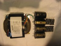
Received the parts for my new Pearl 2 power supply, nice EI core transformer (you recommended this type instead of toroidal), ELNA Audio caps and Vishay Schottky rectifiers (that I had from an other project). I'll be able to compare with the Pearl 1 power supply (Plitron toroidal and Panasonic caps).
Attachments
Hi, the additional resistor I put in is in series with the C10/C11/C14 parallel block. My explanation was just to illustrate how I soldered it in - basically, I took out the leads of the caps from the gate trace and put the resistor in between there. I didnt put a resistor in series with the gate.
thanks for the hint on the collector of the cascode transistor, wayne. That may probably vary also with the current in the device, correct? I noted that in my version both channels had about 23mV across the 10Ohm resistors of the input stage, so the current they are running at is lower than in the schematic that has been shared here (sorry I forgot who that was) with the voltage levels inside. Guess the best way would be to measure the response against RIAA and adjust R11 (and possibly R12) accordingly.
best regards
Hi, the additional resistor I put in is in series with the C10/C11/C14 parallel block. My explanation was just to illustrate how I soldered it in - basically, I took out the leads of the caps from the gate trace and put the resistor in between there. I didnt put a resistor in series with the gate.
thanks for the hint on the collector of the cascode transistor, wayne. That may probably vary also with the current in the device, correct? I noted that in my version both channels had about 23mV across the 10Ohm resistors of the input stage, so the current they are running at is lower than in the schematic that has been shared here (sorry I forgot who that was) with the voltage levels inside. Guess the best way would be to measure the response against RIAA and adjust R11 (and possibly R12) accordingly.
best regards
It seems fairly lower than what I have in my setup, around 43-47 mV if I recall. NP stated to use IDSS matched devices with about 5-6mA IDSS as a minimum . So, top end of the GR grade - as a minimum -, whilst all BL are fine (after matching).
Could you show us a schematic drawing of how you connected the 22 R ? Because now I don't get it
Best,
nAr
I'm planning to make Pearl phono with switchable gain so i can be able to choose between original 55db gain and something about 48db. The idea is to put jumper wire in R15 and a resistor with a jumper parallel to R16 so i can lower resistance then jumper is connected.
Is everything OK this this 'idea'?
Do i have to adjust C9?
Is everything OK this this 'idea'?
Do i have to adjust C9?
Anyone know where a nice, finished chassis like this can be purchased in Canada or the US?
Thanks!
Andrew
Thanks!
Andrew

Enclosure is HiFi2000 Galaxy GX383 10mm silver faceplate, all aluminum, perfect dims for Pearl II boards
Best,
nAr


Hello Andrew
About a year ago I had similar needs, did a quick search, and found nothing comparable in USA or Canada. I ended up purchasing this very same enclosure directly from HI-FI 2000 in Italy. Transport was not cheap, but I am happy with the product.
Feel free to send me a PM if you would like further details.
Pierre
Anyone know where a nice, finished chassis like this can be purchased in Canada or the US?
Thanks!
Andrew
I can only really recommend Par-Metal. They aren't the very prettiest but can be customized a bit and do look quite nice. They can punch holes for connectors and switches if you give them dimensions, and the prices are reasonable... (they don't sell any "pre-configured" that I know of)
AMB uses them to good effect, such as this preamp which is a par-metal, with an extra thick "front" panel for the front and back. I think he had the panels cut by front panel express. (more info on his preamp here)
I compiled a short list of chassis suppliers a couple of years ago. The boutique ones don't stick around long it seems. that thread
Otherwise, it seems most of the good chassis are overseas. Mayeb it's a similar effect to this one: Made in USA
A short essay on why Paul Graham thinks much of the US is ugly ;-)
- Home
- Amplifiers
- Pass Labs
- Pearl Two