Pearl Two issue
Bump.
Replaced the + and - regulators. Supply disconnected from circuit board steady at 35v output at C2 and C3. Connected to circuit board plus supply starts dropping and negative supply starts increasing. Voltage at positive regulator input and output are the same, dropping in synch. Input to negative reg. Climbs but output of 7924 stays at - 24v for a while.
Any suggestions?
I really dont know much about how these things work (I just follow the recipes) but that sounds like your ground plane (or whatever reference your using) is drifting towards one rail.
So perhaps look for something that prevents the ground from draining off current or something that feeds too much current into the ground, in the later case I suspect something would be getting hot?
Are any regulators getting hot?
I guess also this would be consistent with a regulator working opposite and trying to bring the ground up to the intended rail voltage?
"For that project I will use Vishay 1% resistors, Vishay MKP 1% caps for the RIAA correction and bypass output capacitor, Muse for the output ones (22uF/25v); Elna 3300uF/35V and for the 10000uF/40V, the new Mundorf M-Lytics AG séries
Input and output RCA connectors will be Silver Bullet ones "
Nar or anybody sourcing "special" parts; if its possible could you list sources and part numbers I never have much luck locating the special audio parts.
Input and output RCA connectors will be Silver Bullet ones "
Nar or anybody sourcing "special" parts; if its possible could you list sources and part numbers I never have much luck locating the special audio parts.
Nar or anybody sourcing "special" parts; if its possible could you list sources and part numbers I never have much luck locating the special audio parts.
Hi Fritz,
Yes that's terrific to have more than 4 sources or parts. You can try Digikey or Mouser, I had some problems with Farnell so definitely won't buy anything from them again. I deal with RS Components, which are not cheap but they do 24h delivery for free, or Digikey France now available, local dealer here in my place for various, including 2SK170 which I got at 0,70€/pc by 100pc, enough for matching I guess
")
So for parts number, it really depends which source you will choose - the most suitable to you. And is all pleasure to find what you need in the huge parts database
Best regards,
nAr
C9 - Mica okay?
Today's dumb question from a non-engineer:
Is a mica cap the optimal material for C9?
Thanks in advance
P.S. Other dumb question:
My boards came with three packs of 4 of the Toshiba jfets each. I was planning on using one bag for Q6-Q9 for each channel, and then splitting the third bag into the two channels of Q4-Q5. Is this the right approach?
Guys, just finished the pearl two using Pass boards and I have a problem.
Power supply is in a separate box. It checked out ok. But when I connect it to the circuit chassis strange things happen. On turn on things sound fine but within a couple of minutes the volume fades away.
When I checked out the voltages, the positive supply rail at R4 starts dropping from 24.06 volts to around 5.74 volts in about two minutes. The negative rail goes up to 62.1 volts.
This happens with both boards whether one or both are connected to the power supply.
Any suggestions? I have checked the layout and it looks ok. I'm not a techie so I'm a little lost.
Thanks
Rudy
Hi Rudy,
The power supply schematic on the manual, fig 7, have one error. You need to connect the center line of the 2 bridge rectifiers to the center of C2 and C3.
If it is not your case,
maybe you only forgot to connect the Zero Volt line from your separate PS to Pearl II board (pad2-Ground).
Hope it help.
Marcos
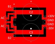
Diode bridges are in standard GBU806 package. I used Digikey part GBU806DI-ND. AC / AC pads are meant for tranny secondaries connection (22 or 24V). C2 & C3 parts are 10.000uF/40V Mundorf M-Lytics caps (25x40mm). There is extra space between caps and diode bridges, in case you would like to mount some heatsinks on the rectifiers. One issue could be the in / out connectors holes sizes + GBU holes size for drilling & soldering though. I might change this in the near future
Last edited:
Oh ! Too sad to hear this I'm sticking with the project however . I now have to match the 2SK170s, received the batch yesterday. I'm going to make the .pdf transparent prints tomorrow. Later on I will order the 1% RIAA polypropylene caps. I will finally need the M-Lytics 10.000uF and a temporary PSU setup to test all this.
Last step will be the enclosure, with the I/O jacks. As I said I will use the Silver Bullet chassis RCAs, but I also need some "power" connectors as my PSU box will be a couple of feet away. Anyone has a good recommendation for this ? I only see the need for 4 wires, the symmetric +/-30V and an optional earth distinct connection from PSU box to main audio one ( as audio ground will be isolated from chassis ) ??? Input appreciated
Best,
nAr
I'm sticking with the project however . I now have to match the 2SK170s, received the batch yesterday. I'm going to make the .pdf transparent prints tomorrow. Later on I will order the 1% RIAA polypropylene caps. I will finally need the M-Lytics 10.000uF and a temporary PSU setup to test all this.Last step will be the enclosure, with the I/O jacks. As I said I will use the Silver Bullet chassis RCAs, but I also need some "power" connectors as my PSU box will be a couple of feet away. Anyone has a good recommendation for this ? I only see the need for 4 wires, the symmetric +/-30V and an optional earth distinct connection from PSU box to main audio one ( as audio ground will be isolated from chassis ) ??? Input appreciated
Best,
nAr
Hmmmm, so I did more reading and started sourcing the parts to try and convince myself to move forward. The only place that I am stuck right now is what to order for P1 and the red led and C7 and C9. I am looking at digikey for P1 and saw this part number. SP064W-5.0K-ND Any help on the other parts would be greatly appreciated.
Hmmmm, so I did more reading and started sourcing the parts to try and convince myself to move forward. The only place that I am stuck right now is what to order for P1 and the red led and C7 and C9. I am looking at digikey for P1 and saw this part number. SP064W-5.0K-ND Any help on the other parts would be greatly appreciated.
SP064W-5.0K-ND for P1 is perfect to my eye, multi-turn Cermet Vishay, will be reliable and precise
red led is part 160-1708-ND or all equivalent 1,8V direct tension red led
for C7 and C9:
C7 is "a good 10 pF" but Wayne stated it could be removed; I chose part 338-1068-ND for this, just in case I would need it;
for C9, use some PTFE insulated wire and twist some length then heat shrink and use a capacitance meter to trim it down with scissors to exactly 5pF and voilà
Last edited:
Appears this isnt going to be the most popular build around here.
I was going to wait and see others projects come to fruition to learn from, but they arent yet coming to the fore.
Looking at other's DIY Pass ONO and similar phono pre builds, I think I see the way I will lay things out. Similar box to my B-1, assuming its wide enough to accomodate the two boards side by side. If not, it will either be made either wider or deeper, so as to hold both boards. Power supply in a seperate case and located underneath the Pearl 2 main box.
How's everyone else planning to lay things out?
Russellc
I plan on sourcing all my parts, get my cabinets, one for the phono boards and one for power supply. Populate the boards and mount everything in the cabinets except the power supply which I will wait to hear what others are doing there. I would expect some activity on builds fairly soon.
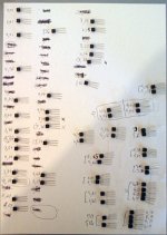
t I'm currently matching the jfets from my batch
So, first batch is matched, out of 60 bought jfets from same wafer, 2SK170 from Toshiba, I got:
- 2 quads >5mA:
@ 6,30-6,29-6,27-6,30 mA
@ 6,16-6,19-6,19-6,13 mA
- 8 pairs also >5mA:
@ 6,01-5,99 mA
@ 5,89-5,88 mA
@ 5,81-5,80 mA
@ 5,78-5,77 mA
@ 5,65-5,66 mA
@ 5,32-5,32 mA
@ 5,15-5,12 mA
@ 5,01-5,00 mA
Is that precision sufficient ? I used a 9V battery with GS tied together and measured the IDSS that way in the 20 mA meter range.
9V battery voltage was the same before and after the matching process, so I guess no fault here.
From the rest I can do some more matched pairs, but they will be below 5 mA IDSS.
May I ask a question ? Do the second stage diff. pair Jfets need to be matched with as high IDSS ? Or is the range from 4 mA to 5 mA still interesting ? I thought the 5 to 6 mA IDSS range was good especially for the input quads ...
Thanks for your input !!!
Regards,
nAr
Attachments
I plan on sourcing all my parts, get my cabinets, one for the phono boards and one for power supply. Populate the boards and mount everything in the cabinets except the power supply which I will wait to hear what others are doing there. I would expect some activity on builds fairly soon.
Sounds like a good way to proceed, to Mouser and digikey!
Russellc
My boards
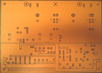
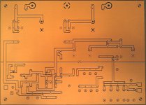
Small update: the boards are now done.
As you can see, this is my attempt to make some real PassDiy Pearl II clone boards
Once again, many thanks to eclectic2k for the big help ! greatly appreciated
Except for the I/O pads, where I added some square areas in order to solder the silver ribbons (remember my version will use no wire to carry audio signals).
I happily used PS for this, though it was a hard time especially for tracks width and ground planes. I then printed my .pdfs to inkjet transparent on my Canon IP3000, and that two times for a good "black" at UVs.
Once varnish is perfectly dry, the drill process will begin. There are about 179 holes x 2 (stereo) to drill. The varnish used was sprayed in very small quantity, so soldering will be easy whilst keeping the tracks away from copper oxidation
Sorry for the blurry & shady pictures. My phone has no flash, but it's a good phone !
Regards,
nAr
Attachments
- Home
- Amplifiers
- Pass Labs
- Pearl Two