I did read somewhere else about the low gain of the Denon . I also don't really have the experience to start getting to clever with changes .
I'll look around for the Dynavector .I have a few contacts here for the that sort of thing .
I noticed my name on the list for the Salas reg . No rush . I might have it finished in time for the Christmas carols. I have an amp project that has taken
priority.
Rich
I'll look around for the Dynavector .I have a few contacts here for the that sort of thing .
I noticed my name on the list for the Salas reg . No rush . I might have it finished in time for the Christmas carols. I have an amp project that has taken
priority.
Rich
Rich,
The Takman and Holco should be on your list, especially the Holco, if they are the original with non-magnetic bodies and leads.
Here's the thing though, in a critical area, like the load resistor, you might want to try something more transparent, like a Charcroft Z-foil bulk resistors. (Other will disagree and feel it is not necessary.) We call them the Nake Vishay Z-foil resistors around here. They are expensive, but there is suppose to be nothing better. I have some for a simple preamp, but haven't had the chance to use them yet.
Cool thing is, once you settle on the value, you can swap them out to see if you get an improvement or not.
I've heard and read good things about Grado, the Blue Note No. 2 and Shure Shure M97xE 2 and Benz Micro. These brands all have reasonably priced carts. I use the Denon 103R. The difference between the 103 and 103r is the purity of the copper winding; the R is better. Mine is outfitted with a Soundsmith ruby stylis and Midas aluminum. However, I won't see the benefits of this cart until I build the Pearl II.")
Have fun and good luck!
Vince
The Takman and Holco should be on your list, especially the Holco, if they are the original with non-magnetic bodies and leads.
Here's the thing though, in a critical area, like the load resistor, you might want to try something more transparent, like a Charcroft Z-foil bulk resistors. (Other will disagree and feel it is not necessary.) We call them the Nake Vishay Z-foil resistors around here. They are expensive, but there is suppose to be nothing better. I have some for a simple preamp, but haven't had the chance to use them yet.
Cool thing is, once you settle on the value, you can swap them out to see if you get an improvement or not.
I've heard and read good things about Grado, the Blue Note No. 2 and Shure Shure M97xE 2 and Benz Micro. These brands all have reasonably priced carts. I use the Denon 103R. The difference between the 103 and 103r is the purity of the copper winding; the R is better. Mine is outfitted with a Soundsmith ruby stylis and Midas aluminum. However, I won't see the benefits of this cart until I build the Pearl II.
Have fun and good luck!
Vince
Last edited:
saving a little is always nice.
Nothing wrong with that; just so long as you know that the alternatives exist.
On one of my boards I'm seeing unstable voltage at R17. It drifts 2-300 mv after a short time. Should I replace P1?
Did you implement C7 ? Wayne stated that boards finally wouldn't need them, especially if you use ZVP3310 and Pearl II original layout ...
It would give some instability problems to some users if I recall.
nAr
Did you implement C7 ? Wayne stated that boards finally wouldn't need them, especially if you use ZVP3310 and Pearl II original layout ...
It would give some instability problems to some users if I recall.
nAr
C7 is removed and voltages are stable now
I also implemented your ground scheme by grounding the outputs to the PS ground, isolated from the case, and grounding the case to earth.
Mark
So, I've been spinning records, and I still have some grounding problems. Touching various parts of the unit makes the ground buzz worse, or go away.
Touching the metal case, which is grounded to earth, makes the buzz go away. Same with touching the interconnect grounds.
Waving my hand near the wires connecting the input jacks to the board make the buzz louder, and touching these wires makes it very loud. The + and ground wires from the input jacks are twisted together. Any ideas for eliminating this?
Mark
Last edited:
Logically each input from cart has its own ground. You can rewire by leaving each ground "alone" at outputs if you have 2 distinct supplies.So, I've been spinning records, and I still have some grounding problems. Touching various parts of the unit makes the ground buzz worse, or go away.
Touching the metal case, which is grounded to earth, makes the buzz go away. Same with touching the interconnect grounds.
Waving my hand near the wires connecting the input jacks to the board make the buzz louder, and touching these wires makes it very loud. The + and ground wires from the input jacks are twisted together. Any ideas for eliminating this?
Mark
You can also try star grounds in between each channel. You can link audio ground to earth via 10R / 1W or more resistor, or via a CL60 thermistor.
Did you implement the 3rd bridge in the supply from Wayne ?
1) verify from input jacks from TT that each channel from cart has distinct GND
2) TT has a GND wire alone, that must be wired to audio GND if I recall
Can you share pics of your realisation ? Could be helpful. Thanks
Here's my build. As you can see, I lined the wood case with aluminum sheet. This sheet is grounded to earth. The top is powder-coated steel. I also made an aluminum sheet for the bottom.
The black (-28v) red (+28v) and green (ps ground, not grounded to earth) come in to the case. The green goes to the board grounds and to the binding post, isolated from the case. The binding post connects to the output grounds and the TT ground.
You can also see I'm using two wires twisted together per channel.
What I'm seeing is that bringing my hand close to, or touching, the input wires at the bottom will make a buzzing sound. Touching the input wire and the aluminium liner at the same time makes the buzzing disappear completely. Also, touching the metal tops of the caps makes the buzz go away.
Any suggestions?
An externally hosted image should be here but it was not working when we last tested it.
My 2C:
Its worth trying to solve this by rearranging your ground a little. First off, try and replace the input wiring with shielded cable. Then tie all shields together at one star point - where your PS ground also goes to. Lastly, connect the ground lug of your inputs to ground via a 0.01uF cap (any cheap ceramic). Its important that this cap is grounded with as short as possible leads between ground lug and case ground. Long leads = useless. Looking at your case, it might be worth changing your layout a little so that the 2 inputs are beside each other, and then the 2 outputs are the other side of the case.
Solved exactly your kind of issue before for me....
Fran
My 2C:
Its worth trying to solve this by rearranging your ground a little. First off, try and replace the input wiring with shielded cable. Then tie all shields together at one star point - where your PS ground also goes to. Lastly, connect the ground lug of your inputs to ground via a 0.01uF cap (any cheap ceramic). Its important that this cap is grounded with as short as possible leads between ground lug and case ground. Long leads = useless. Looking at your case, it might be worth changing your layout a little so that the 2 inputs are beside each other, and then the 2 outputs are the other side of the case.
Solved exactly your kind of issue before for me....
Fran
Thanks. I happen to have some Mogami Neglex 2534 microphone cable that I can use for the inputs. Should I use two shielded cables per board, one cable for + and one for -? Or can I use one per board with + and - in one shielded cable?
Also, does the .01uf cap connect to earth ground or PS ground?
Here's my build. As you can see, I lined the wood case with aluminum sheet. This sheet is grounded to earth. The top is powder-coated steel. I also made an aluminum sheet for the bottom.
The black (-28v) red (+28v) and green (ps ground, not grounded to earth) come in to the case. The green goes to the board grounds and to the binding post, isolated from the case. The binding post connects to the output grounds and the TT ground.
You can also see I'm using two wires twisted together per channel.
What I'm seeing is that bringing my hand close to, or touching, the input wires at the bottom will make a buzzing sound. Touching the input wire and the aluminium liner at the same time makes the buzzing disappear completely. Also, touching the metal tops of the caps makes the buzz go away.
Any suggestions?
I would do a decent Star Ground.
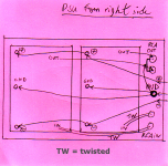
Using your GND jack for TT ground, as a Star. See attached. I moved PSU input to the right for more consistance.
The + and - distribution "in chain" is acceptable, even if I wouldn't.
But Ground needs a special treatment not to catch any noise.
Make cables short as possible, but no vicinity of big electrolytics for GND wires.
Sorry it's done quick n' dirty, but I hope readable. Inputs don't need shield, a twisted pair with + / GND shound be sufficient.
Still all metal parts of the case direct to Earth. You can then link the Star Ground to Earth (chassis) but not direct, use 10R/1W or CL60.
Can you try this ?
Best,
nAr
Attachments
Thanks nar. Looking at your picture, the only things that are different from my build are:
1: The binding post needs to connect to earth ground through a resistor
2: The output leads are not twisted.
Is this right?
Do you recommend separate lines from the PS to each board?
Mark
1: The binding post needs to connect to earth ground through a resistor
2: The output leads are not twisted.
Is this right?
Do you recommend separate lines from the PS to each board?
Mark
Have a read through the info at the link below :
Star Grounding
It's about the best summary on grounding I've come across. So connect the ground lugs to chassis ground via the caps, your signal ground can also connect here. If doing that causes hum, put a pair of diodes err, 69 style, back to back with a 10r power resistor and a 0.001-0. 01uf cap in parallel between signal stars and chassis ground.
Fran
Thanks nar. Looking at your picture, the only things that are different from my build are:
1: The binding post needs to connect to earth ground through a resistor
2: The output leads are not twisted.
Is this right?
Do you recommend separate lines from the PS to each board?
Mark
Nope, look closely
Your PSU input is at the left, and to me you don't Star Ground, you "chain" grounds to the 1st board, then 2nd board then to the TT GND on the right, then you put that ground at the outputs RCAs.
Am I mistaken ?
I would also suggest you turn your boards and arrange to get the PSU input in between the 2 boards maybe, and so for the TT ground binding post and all RCAs, it would also give you shorter Ground paths
nAr
Ah, got it! I'll try it today.
- Home
- Amplifiers
- Pass Labs
- Pearl Two