Things looked pretty normal voltage wise until I got to Q3. The E leg is 11.5volts and the C leg is .1mv, so I’m guessing I zapped that guy while removing or replacing the linear voltage regulators. I did catch myself without my wrist strap on a couple of times, perhaps that’s the cause. Having read all the posts in the Pearl Two and Building a Pearl Two threads I ordered extras of ZTX450 power transistors which I will be replacing tonight. 🤞
Pearl Two is up and running again and even better than before! After replacing Q3 it still didn’t measure out so I went back to Q1 which was dead. Either it was dead before and I neglected to measure it or I killed Q1 while replacing Q3. With both replaced the Pearl Two is sounding better than before I messed it up! Prior to changing Q1 and Q3 there was a slight hiss in the left channel (which I was unfairly blaming on my 300b Audio Nirvana amp, by the way this is an amazing sounding 300b amplifier), which has miraculously disappeared! Troubleshooting was actually fun.
Again, thank you so much to everyone for every post before me! I’ve learned some things with this project, which is great in itself, and it has given me the confidence to build an Aleph J. This is because of others willing to share information, their time, and effort. Starting with Nelson, Wayne, and Jim and including that person that made a single comment that turned on a light bulb for me, all of the participants. Also thanks DIYAudio store, it is great to have the resource!
Again, thank you so much to everyone for every post before me! I’ve learned some things with this project, which is great in itself, and it has given me the confidence to build an Aleph J. This is because of others willing to share information, their time, and effort. Starting with Nelson, Wayne, and Jim and including that person that made a single comment that turned on a light bulb for me, all of the participants. Also thanks DIYAudio store, it is great to have the resource!
I think you will find the Aleph J easier than the Pearl 2.
I guess I was lucky, my Pearl 2 fired up right off and worked fine with no zapped 3310 or anything. Other than normal precautions, I used no static wrist devices, just a solder gun.
I want to install the cap that seems to zero and stabilize the offset, but I hate messing with something that works....
Russellc
Last edited:
Russellc I hear you on not messing with a working Pearl. I should have installed the heatsinks from the beginning but in the end I’m really happy to have had the troubleshooting experience, especially since it turned out so well. You sure posted some helpful info and questions so you too are on the ‘grateful you are here list’. Thank you.
Well, thanks but I'm still a babe in the woods with all this...There is a reason I ask so many questions!
I can Id parts, follow a schematic and solder fairly well. I would never have built all I have built (such that it is, many are WAY ahead of me) without the knowledge and patience of members here.
The internet and digital cameras have really been a giant help to the whole diy community.
Russellc
I can Id parts, follow a schematic and solder fairly well. I would never have built all I have built (such that it is, many are WAY ahead of me) without the knowledge and patience of members here.
The internet and digital cameras have really been a giant help to the whole diy community.
Russellc
Pass DIY Addict
Joined 2000
Paid Member
Scott: Great to hear that you solved your problem! I've been tied up with work lately and a little behind on messages. I was going to suggest looking at your regulators again as well as some of the other more sensitive transistors.
Russell: doing the mod to remove the DC offset is worthwhile. It was pretty easy to accomplish and moved a "floating" few mV of offset to a rock-steady 0.0mV.
The next mods that I want to try are adding Salas' shunt regulators and replacing some of the 0.1uF film caps with some NOS Russian teflons. This might be a trick, though, as the Russian teflons are HUGE caps. I'll need some way to strap or glue them down.
The next mods that I want to try are adding Salas' shunt regulators and replacing some of the 0.1uF film caps with some NOS Russian teflons. This might be a trick, though, as the Russian teflons are HUGE caps. I'll need some way to strap or glue them down.
The noise performance of P-2 is excellent and i could see no improvement when i removed the Nat Semi regulators and fed the circuit with +/- 24 Superregulators.
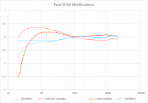
If you are planning to tweak the design, adjusting the RIAA component values gives the best bang for the buck.
Pass DIY Addict
Joined 2000
Paid Member
A question about voltage regulators: the LM317 is often suggested as a low noise alternative to the 7824. Looking at datasheets there are 7824's with 10uV/Vo noise (so 240uV for 24V out), while the LM317 noise is specified as 0,003% of Vo, which would be 720uV at 24V out. Ripple rejection is a lot better for the LM317 though.
So is the LM317 still better than the 7824 in the Pearl2, or should I be looking for other low noise voltage regulators? (I want to keep it simple, no shunt regs etc)
So is the LM317 still better than the 7824 in the Pearl2, or should I be looking for other low noise voltage regulators? (I want to keep it simple, no shunt regs etc)
Thanks for the reminder on the RIAA changes, Jack. I made some notes from your original post on this topic some time ago. I noticed in your graph that the units displayed were on the order of 0.25 and 0.5dB. How audible of an impact were these changes you made?
Dont' tell anybody -- the only time you'll hear a difference is when the two channels aren't matched to each other. As most of my vinyl dates from the 1960's and 1970's other things are much more bothersome.
If you are going to invest the time on a Pearl 2, probably worth buying a 10 pak of the two RIAA filter caps OR invest in an assortment of smaller value caps which you can tack solder in until you get two curves which resemble each other.
A question about voltage regulators: the LM317 is often suggested as a low noise alternative to the 7824. Looking at datasheets there are 7824's with 10uV/Vo noise (so 240uV for 24V out), while the LM317 noise is specified as 0,003% of Vo, which would be 720uV at 24V out. Ripple rejection is a lot better for the LM317 though.
So is the LM317 still better than the 7824 in the Pearl2, or should I be looking for other low noise voltage regulators? (I want to keep it simple, no shunt regs etc)
The noise performance of the LM317/LM337 benefits from putting an electrolytic from ADJ to GND. To large a value, however, will cause the transient performance to suffer. 10uF should suffice.
LM337 CAN NOT be soldered directly onto the PCB -- will require a little leg bending, etc., etc. LM7924 is not a routinely stocked part (except at Rochester) so you'll have to consult the datasheet. You can also use another negative regulator with a zener in the GND pin to compensate for the higher required voltage.
I'm currently running the Pearl2 with 7824/7924's. The 7924 is even specified a bit better for noise than the 7824 at 170uV (24V out). I probably will not hear much of a difference but I have the urge to tweak something ;-) I also want to make load, capacitance and gain selectable with dip switches.
Wayne,I have moved away from the TO-92 MOSFETs they are very static sensitive little buggers.
Any recommendations for substitute? Or use the SOT23? I have killed 2 and even now I'm not sure what's one mine is 100% alive as the seems to be extra distortion compare to my other preamps?
I have my Pearl2 working good for a few months, but this afternoon, a problem appeared while I was listening some records: randomely, the sound on the left channel disappeared and came back again.
I started some troubleshooting:
-I tried with a CD and no problem occured, so amplifier and speakers are OK.
-I inverted left and right channel on the headshell leads and still had intermittent failure on the left channel, so cartridge seems to be OK.
-I inverted left and right channel on the input on the Pearl2 and, this time, failure appeared on my right hand speaker. So I suspect there's a problem on the left channel of my Pearl2.
I'll open it to see what I can find, but the failure being random (for example, I just finished to listen a side of a 45rpm 12" having only a 3 or 5 seconds failure...), I don't really know what to check.
Does anybody have any clues?
Last edited:
Wayne,
Any recommendations for substitute? Or use the SOT23? I have killed 2 and even now I'm not sure what's one mine is 100% alive as the seems to be extra distortion compare to my other preamps?
I have not seen any failures in the ZVN2110 smt version.
- Home
- Amplifiers
- Pass Labs
- Pearl Two