Happy hollidays, guys.
Is R12 of critical value? I have a resistor of around 905R installed in this position, but I have found .1% 909R in my bin, I could use to replace it.
Not critical --
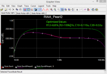
But to tweak the Pearl 2 -- instead of 909 use 990 (which is 1K in parallel with 100K, (or just 1K)) and make the slight adjustments to the capacitor values.
Attachments
Not critical --
But to tweak the Pearl 2 -- instead of 909 use 990 (which is 1K in parallel with 100K, (or just 1K)) and make the slight adjustments to the capacitor values.
In the picture you have C10=0,11u and C20=0,32u. I guess you mean C10 = the sum of C10,11 and 14 in the original schematic (now 0,12u) and C20= sum of C17-20 (now 0,333).
I'm thinking about a rebuild of my Pearl using the Passdiy boards for later this year. Can't stop the urge for further tweaking ;-) Does anyone know how close the FET's that come with these boards are matched?
I hope to lower the noise (hiss) a bit in comparison to my current version. Any tips? Vishay RN series resistors in stead of CMF? Are there lower noise versions of the 7824 and 7924? (I'd like to stick to the original design)
I hope to lower the noise (hiss) a bit in comparison to my current version. Any tips? Vishay RN series resistors in stead of CMF? Are there lower noise versions of the 7824 and 7924? (I'd like to stick to the original design)
I hope to lower the noise (hiss) a bit in comparison to my current version. Any tips? Vishay RN series resistors in stead of CMF? Are there lower noise versions of the 7824 and 7924? (I'd like to stick to the original design)
Do you have hiss when the input is shorted?
WRT the voltage regulators -- try LM317/LM337 -- don't use the 120R between OUT and ADJ, rather 1.1K. The resistor from ADJ to ground then becomes 20K, a standard value. Place 4.7uF across the 20K. This combination results in a huge decrease in regulator noise and better transient response. WJ mentioned it in his 1995 regulator articles. There is enough current drawn by the circuitry to keep the regulator stable with these new resistor values.
You can do one better by using Jan's regulator boards from the DIYAUDIO store.
BTW -- 7924's are pretty much unobtanium, having gone EOL. Rochester Electronics has plenty, but they're not particularly easy deal with owing to export restrictions, etc.
Attachments
In the picture you have C10=0,11u and C20=0,32u. I guess you mean C10 = the sum of C10,11 and 14 in the original schematic (now 0,12u) and C20= sum of C17-20 (now 0,333).
The Pearl PCB's are quite easy to set up for experimentation -- I use machined female headers into which I can insert components of different value, then check the performance against the RIAA curve. Theoretical values get you about 70% of the way, but parasitics aren't easy to model.
Attachments
thank you for your comments, I will look into the LM317. I can always use the 7924 I already have in my current Pearl, but lower regulator noise has to be better I guess ;-)
If you're using Wayne's boards you would be well advised to check the pinouts if you use a modified variable regulator.
That is wise advise ") Still thinking about Wayne's boards. Shipping to Europe is $45, 21% VAT and some customs charges will make these very expensive boards. Either use my birthday money in few months time or just modify my current Pearl first. I can always rebuild it on the original boards later.
Still thinking about Wayne's boards. Shipping to Europe is $45, 21% VAT and some customs charges will make these very expensive boards. Either use my birthday money in few months time or just modify my current Pearl first. I can always rebuild it on the original boards later.
Still thinking about Wayne's boards. Shipping to Europe is $45, 21% VAT and some customs charges will make these very expensive boards. Either use my birthday money in few months time or just modify my current Pearl first. I can always rebuild it on the original boards later.The gerber files are freely available as a zip file on the PassDIY site -- if you're going to go this route, you might want to put pads for the surface mount BF862 in place of or in addition the K170's. You could also change the power supply regulator configuration for the LM317/337 as I suggested earlier.
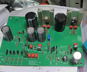
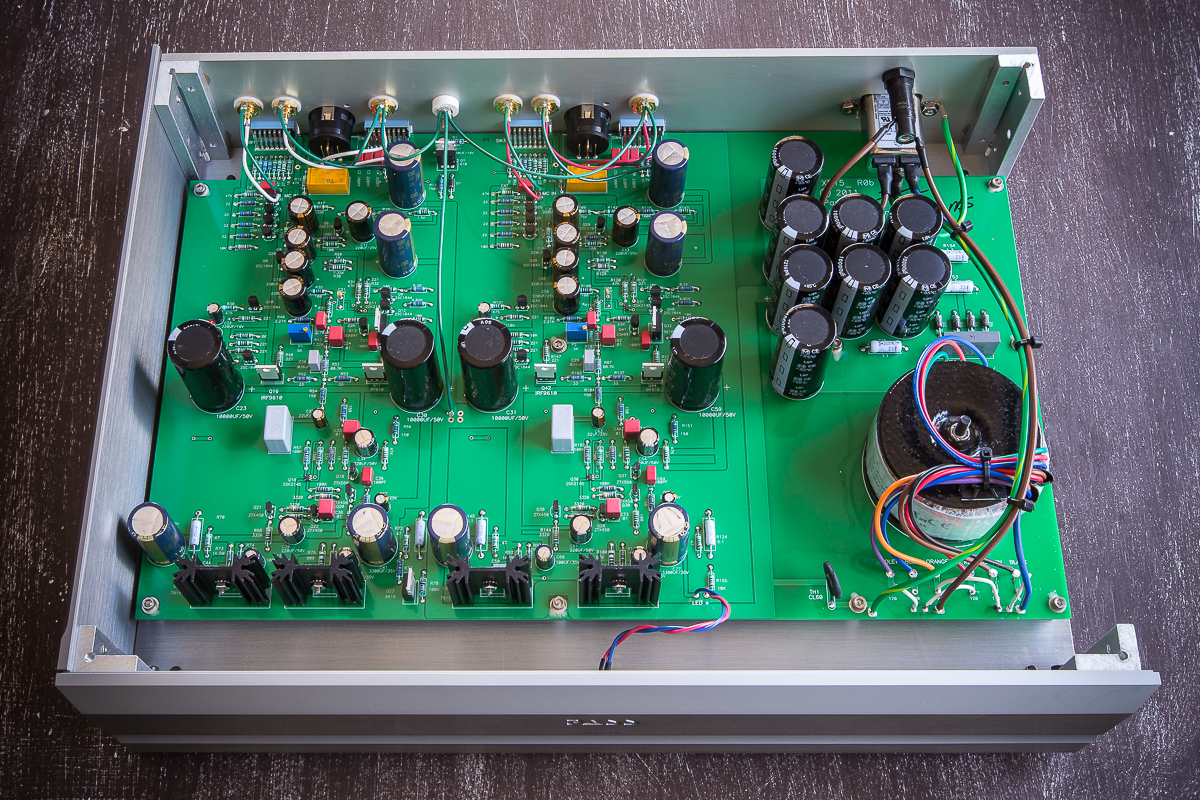
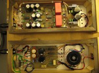
To keep the bulk of the ripple current contained in one bridge and the first two filter caps.
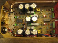
Then there is an incredible amount of CRC, followed by regulators, and lots of local decoupling.
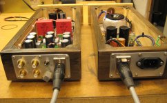
Looking at this photo, you can see that there is more PSU capacitance in this preamp than a Firstwatt Power Amp.
Cool.
Then there is an incredible amount of CRC, followed by regulators, and lots of local decoupling.
Looking at this photo, you can see that there is more PSU capacitance in this preamp than a Firstwatt Power Amp.
Cool.
One thing is still confusing me: Why all commercial Pass Lab phono preamps (including expensive XP-25) have single bridge CT transformer raw power supply? At the same time they suggest dual bridge approach in Pearl Two as the optimal solution.
I can't speak for the design of the commercial Pass equipment, but in the Pearl 2 whitepaper, Wayne recommends the dual bridges due to the imbalance of current drawn from the positive and negative supplies. And as 6L6 said, they appear to have much more filtering on the commercial products to overcome any noise that would exists.
6L6, why are you using dual bridge in your Pearl Two then? Dual bridge PS isolates power transformer from preamp GND with all the benefits.It also reduces diode bridge noise. XP-15 you have showed here has different current on V+ and V-, and it is ideal for dual bridge power supply. Its power supply is ordinary single bridge, not even dual mono power supply with brute force filtering. No one forced Mr. Colburn to recommend dual bridge PS in Pearl Two .
Perhaps saving in cost of four soft recovery diodes in 3,5K dollars preamp is significant in manufacturing.
Perhaps saving in cost of four soft recovery diodes in 3,5K dollars preamp is significant in manufacturing.
7812 and 7912 regulators with voltage dividers to increase voltage to 24V as in datasheet reduce noise and ripple. Better to me than LM 317/337.The gerber files are freely available as a zip file on the PassDIY site -- if you're going to go this route, you might want to put pads for the surface mount BF862 in place of or in addition the K170's. You could also change the power supply regulator configuration for the LM317/337 as I suggested earlier.
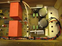
Why am I using dual bridge? A few reasons -
The transformer I had on hand was dual secondary.
I had a really nice dual bridge PCB.
Original schematic shows dual bridge.
FWIW, the transformer in the XP-15 appears to be CT, not dual secondary. Perhaps there was something particular about that transformer that made it the better choice than another, and that's why there is one bridge. It may be easier to snub the diode noise of a single bridge... ? Regardless, the amount of CRC in that preamp is going to make any dissimilar current imbalance reflected back into the windings completely insignificant.
One more Pearl 2
Hello guys.
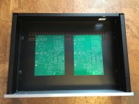
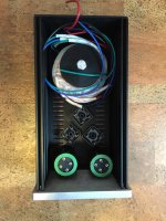
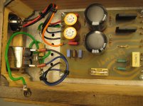
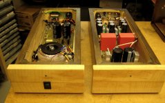
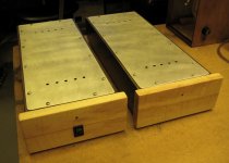
As a first time writer in DIYAudio I like to show you my newly finnished Pearl 2. I'ts kind of low budget model. I've done the boards myself, the boxes to and tryed to use as much old components as I had lying around as possible. I have as you maybe can se a switch MC/MM. I'm letting one relay switch a 100 ohm resistor parallell to 47k at the inlet and another relay to short R15 where I used 220 kohm. I'm now mostly using a Denon DL 103R pickup and it works just fine. I've also tested with MM Ortofon OM30 and it works just fine to. Another thing, I used only one regulatorboard for the supply voltage. And so far no problems what I can see or hear.
One thing, that I've seen being discussed previusly in this thread, is oscillation problems. And when I first switched the P2 on and locked at the scope I was very dissapointed. Terrible oscillation in the output region. Tryed first to put in C15 I think 100pF. Better but not good. Then I tryed to increase C7. No sucsess.
Finally tock C7 away. No sign of oscillation!!
Now im using the Pearl in my main stereo-setup and it works just fine. No hiss, no hum just nice music.
Hello guys.
As a first time writer in DIYAudio I like to show you my newly finnished Pearl 2. I'ts kind of low budget model. I've done the boards myself, the boxes to and tryed to use as much old components as I had lying around as possible. I have as you maybe can se a switch MC/MM. I'm letting one relay switch a 100 ohm resistor parallell to 47k at the inlet and another relay to short R15 where I used 220 kohm. I'm now mostly using a Denon DL 103R pickup and it works just fine. I've also tested with MM Ortofon OM30 and it works just fine to. Another thing, I used only one regulatorboard for the supply voltage. And so far no problems what I can see or hear.
One thing, that I've seen being discussed previusly in this thread, is oscillation problems. And when I first switched the P2 on and locked at the scope I was very dissapointed. Terrible oscillation in the output region. Tryed first to put in C15 I think 100pF. Better but not good. Then I tryed to increase C7. No sucsess.
Finally tock C7 away. No sign of oscillation!!
Now im using the Pearl in my main stereo-setup and it works just fine. No hiss, no hum just nice music.
Attachments
Hello guys.
I like to show you my newly finnished Pearl 2. I'ts kind of low budget model. I've done the boards myself, the boxes to and tryed to use as much old components as I had lying around as possible.
Now im using the Pearl in my main stereo-setup and it works just fine. No hiss, no hum just nice music.
Very nice, Abrandt!
I was following your way as well at building the Aleph-X and the Bride of Zen, using home-made PCBs and (possibly) parts lying around. I am sure that the resulting sound quality could be much higher with rare and expansive parts, but procuring them were practically impossible hier, in Hungary. However, I am very pleased with their sound and decided to complete the system with a phono stage.
I were interesting for your PCB solution: could you append something about it, please? I am certainly not the only with this curiousity...
- Home
- Amplifiers
- Pass Labs
- Pearl Two