My Pearl 2 has a 100 ohm resistor installed in the R20 position. Specifications call for 100 ohm loading on the cartridge I'm using. I need to demo a turntable/cartridge I'm selling which specifies a 47k ohm load. What happens if I hook it up with the Pearl 2 configured the way it is?
Just remove the 100R resistor from pins for the demo, and put it back afterwards
Best,
nAr
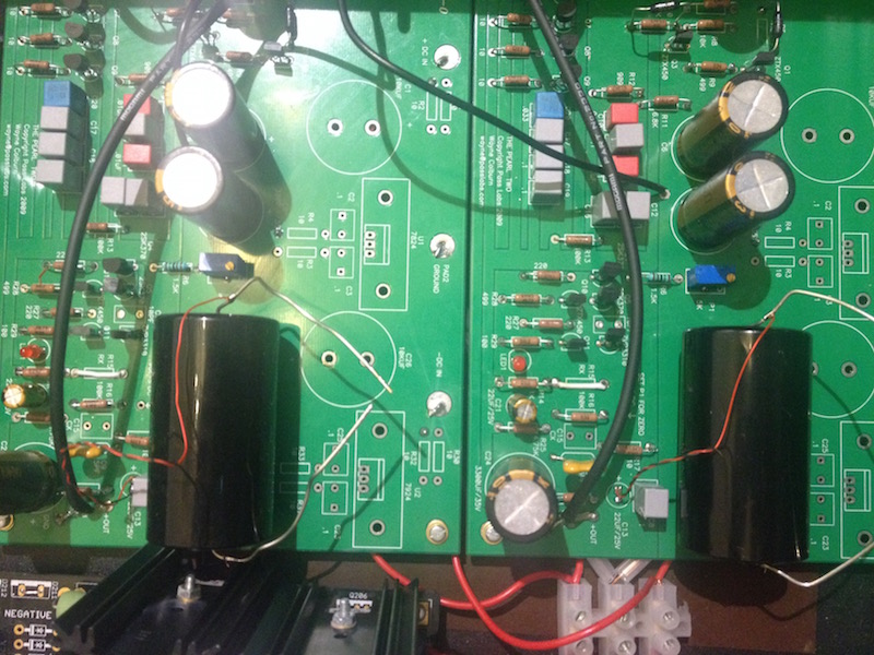
I have received some output caps from a very generous and helpful man – Jim aka 6L6 so I'm testing them in following combinations:
1. Silmic II 10uF + .1uF film
Smoooth and silky, nice dynamics and overall love, love, love...
2. Silmic II 10uF and radial Mcaps 2.7uF for bypass.
Superb presentation and even more natural sound, great imaging. Love again. Although, not that convincing in lower register and transients not satisfactory.
Do you guys think my radial caps leads mess could affect the performance somehow?
Just remove the 100R resistor from pins for the demo, and put it back afterwards
Best,
nAr
That's what I did. Thanks
I'm still investigating Pearl. It seems that 2sk170 has failry high input capitance (30pF). So with quad on input it will give additional 120pF?
If so it will not be the best match for most MM's any way.
My next cart will be HOMC so it's not a problem for it any way.
Most phono cables will give you this kind of amount of capacitances anyway.
In the pearl II the k170 quad is cascoded so you will not have bad Miller effect on the voltage gain obtained, if I recall properly.
Best,
nAr
Last edited:
Most phono cables will give you this kind of amount of capacitances anyway.
In the pearl II the k170 quad is cascoded so you will not have bad Miller effect on the voltage gain obtained, if I recall properly.
Best,
nAr
That is exactly true. Cables will give you something around 100pF, input stage will give you another 120pF. And most of MM's works best with capitance around 100pF total (despite what manufacturers are claiminng).
For me this quad looks parallel.
That is exactly true. Cables will give you something around 100pF, input stage will give you another 120pF. And most of MM's works best with capitance around 100pF total (despite what manufacturers are claiminng).
For me this quad looks parallel.
Yes exactly, quad = paralleled, ... but, ... I think the input capacitance of the quad devices is lowered a lot by the use the a cascode if I recall.
From "Jfets, The New Frontier, Part 1" awsome article by E. Borbely. Truly basic, inspired, documented, and soulfull ...
" Cascode to the Rescue
There is another way of reducing
the input capacitance of the amplifier.
Cascode connection of devices was invented
in the tube era, but has also been used
extensively with bipolar transistors.
One of the advantages of cascoding, if you recall,
is reduction of input capacitance,
which makes it easier to design high-frequency amplifiers. "
Best,
nAr
Subjective evaluation of four capacitor setups is a bit too much to handle for my memory. I can't tell firmly which pair was overall best on the output. I've passed an evening with each. No beer involved! That's what I think I remember:
22uF Silmic and 2.7uf huge (800 V) radial MCAP. Best overall transparency. Nice stage and distinguishes recording ambients best between different LPs.
10uF Silmic and .1 film was second best. Nice grip and transients. I also listened to this combination first. Thus it's the most difficult to recall.
22uF Silmic and .1 film Nice, but lacks distinguishing features when compared to together
10uF Silmic and 2.7uF huge (800 V) radial MCap. Clear, smooth mid and highs a bit shy in the lower register.
Does that make any sense?
Were there any measurements I could perform and compare?
Cuts on the Miller (multiplication of capacitance by voltage gain). The static input value remains.
So we have 120pF of capitance and 30dB gain for first stage which is x30 voltage gain so input capitance sould be 4pF?
That looks much better.
You surely got Ciss*4=120pF plus little internal cabling & board parasitic. Its you are cascoding to avoid multiplying the Crss by 30. Cascoding does not always kill Miller 100% though, depends on how high are the source resistors too. To know for sure, someone's got to measure an input stage's frequency response using different voltage source resistance and compare F3 to calculate the apparent capacitance. By just supposing it could be somewhere in the 120pF-200pF range as is.
My current capitance for IC and turntable internal wiring is 80pF, current phono (VSPS) has 30pf + 10pF (Opa2604) so its about 120pF total. My goal for most MM's would be to keep below 120pF to have resonance above 20khz.
Anyway next cart is HOMC so it will be immune to capitance level (in this range).
Anyway next cart is HOMC so it will be immune to capitance level (in this range).
Last edited:
Most MM will not manage enough HF due to largish moving mass without the aid of the electrical resonance in the top octave. The few finer ones like an AT150MLX with thin boron cantilever and MicroLine stylus would benefit from low pF. They only sound brighter than heavier moving mass MM carts for the reason they already got response and it gets a non needed boost by excess capacitance. Varying the Ohmic load can help though. 47K ain't necessarily written in stone.
In any case you will be better off with a HOMC for this 4X JFET input stage. Free to load correctly and have the response there without tricks. SNR will still be fine.
In any case you will be better off with a HOMC for this 4X JFET input stage. Free to load correctly and have the response there without tricks. SNR will still be fine.
Subjective evaluation of four capacitor setups is a bit too much to handle for my memory. I can't tell firmly which pair was overall best on the output. I've passed an evening with each. No beer involved! That's what I think I remember:
22uF Silmic and 2.7uf huge (800 V) radial MCAP. Best overall transparency. Nice stage and distinguishes recording ambients best between different LPs.
10uF Silmic and .1 film was second best. Nice grip and transients. I also listened to this combination first. Thus it's the most difficult to recall.
22uF Silmic and .1 film Nice, but lacks distinguishing features when compared to together
10uF Silmic and 2.7uF huge (800 V) radial MCap. Clear, smooth mid and highs a bit shy in the lower register.
Does that make any sense?
Were there any measurements I could perform and compare?
It does make sense indeed but to be fair, you should test same total capacitance value at a time, and have like 4 short extracts from different lps, leave the caps in for burn in the same time (at the point they're burned) and proceed to test your combos, ... Then, most hard part, ... Which sounds the best for you, or the combo you could live with !!!! ��
Best,
nAr
Nar, your comment makes a total sense and sounds like a reasonable procedure.
[..] The few finer ones like an AT150MLX with thin boron cantilever and MicroLine stylus would benefit from low pF. They only sound brighter than heavier moving mass MM carts for the reason they already got response and it gets a non needed boost by excess capacitance. Varying the Ohmic load can help though. 47K ain't necessarily written in stone.
In any case you will be better off with a HOMC for this 4X JFET input stage. Free to load correctly and have the response there without tricks. SNR will still be fine.
On a start I was actualy considering AT150MLX but finnaly I have chosen Denon DL-110 for little bit less $.
So it's time to start collecting parts for Pearl.
- Home
- Amplifiers
- Pass Labs
- Pearl Two