I have tried controlling DC offset with suggested methods: measuring when the cover is on and when the phono stage has warmed up. Didn't help. It is very prone to ambient variations. I can see a clear rise in DC when the cover is on and going down when it's off. When I blow air into the box it becomes very jumpy.
What could help?
Base resistor on Q3?
TO92 heatsinks (double) that I have somewhere?
Maybe I'm setting my gain wrong?
What could help?
Base resistor on Q3?
TO92 heatsinks (double) that I have somewhere?
Maybe I'm setting my gain wrong?
I'm sure it can be solved without DC servo and AC coupling. I wonder if raising R21-R24 to 20R could help the problem? Here are my approximate voltages (attached) vs Wayne's voltages
Attachments
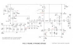
Oh I had completely forgotten the circuit. It is AC coupled of course.
What voltage are you worried about? Since it's AC coupled anyway, I'd say just use it. The DC cannot hurt your following equipment because it's AC coupled. If you are worried about the operating points of the devices, just put the lid on and it should stabilize.
What voltage are you worried about? Since it's AC coupled anyway, I'd say just use it. The DC cannot hurt your following equipment because it's AC coupled. If you are worried about the operating points of the devices, just put the lid on and it should stabilize.
Although, there's something wrong either with my gain calculation,
or the gain setting resistor.
In theory it should be set be around 66 dB, while it's 46 dB at the moment.
Confirm your loaded input signal level by using an extra channel of the scope with a probe attached across the phono stage's input jack, while displaying the phono output already through another channel.
nar, Bkdog, Salas
Yes, silly me of course it's AC coupled.
Fets are per BOM 2SK370 Toshibas from Pass.
I'll put the phono under the scope again to double check the gain.
Even you suggest, I shouldn't be worried, that offset still puzzles me.
Something's different to other users and Waynes version.
Yes, silly me of course it's AC coupled.
Fets are per BOM 2SK370 Toshibas from Pass.
I'll put the phono under the scope again to double check the gain.
Even you suggest, I shouldn't be worried, that offset still puzzles me.
Something's different to other users and Waynes version.
Well, do you mean the offset at the node between R16 & R17?
I am not surprised that the increased gain (and less feedback) makes it less stable at DC. You could lift one leg of C16 and see if that improves things.
Check the overload behaviour, increase the 1KHz sine wave until it clips, if the offset is poor it will clip asymmetrically and that is a good reason to keep the DC under control.
Good luck!
C12 and C16 AC couple the first stage to the second stage, looking at it quickly it looks like the -3dB point is about 8Hz. Removing one of the capacitors (both 0.1uF) halves the C and doubles that turnover point to about 16Hz - still low enough and it might filter out some LF fluctuations coming from the first stage.
Thank you! Your attention much appreciated.
I'll try measuring offset as suggested.
Although, there's something wrong either with my gain calculation,
or the gain setting resistor.
In theory it should be set be around 66 dB, while it's 46 dB at the moment.
Remember that the Eq is passive and you lose a lot in it.
Well, with 300R gain setting resistor I should be closer to 66 dB rather than 46 dB territory anyway.
With some weekend duties I am away from home and scope at the moment. Just a thought, could it be that I messed up matched fets somehow, in a way that voltages dont match to Pass labs ones?
With some weekend duties I am away from home and scope at the moment. Just a thought, could it be that I messed up matched fets somehow, in a way that voltages dont match to Pass labs ones?
Well, with 300R gain setting resistor I should be closer to 66 dB rather than 46 dB territory anyway.
With some weekend duties I am away from home and scope at the moment. Just a thought, could it be that I messed up matched fets somehow, in a way that voltages dont match to Pass labs ones?
Na, on looking at the circuit again it's most probably the second gain stage that's giving you grief, Q4 & Q5, you could try grounding the gate of Q4 and see if that improves the offset fluctuation. If you still have fluctuating offset with the gate of Q4 grounded, then it's definitely in the second stage, if it fixes things then it is either Q4 or earlier.
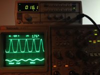
The overload margin on the output looks small. 50 Ohm lab gen standard produces double than displayed when in kOhm range loads. What is the 1kHz RMS with DMM on AC mode for input and output if you will take a couple of readings across the RCAs while the Pearl is hooked up on the scope and gen? Adjust for max non clipping output first.
8mV RMS is too much of an input for MC, lets make sure its not the input stage clipping first. Use 4.7k in series to 47 Ohm across (L-Pad). That will give you 1:100 attenuation i.e. 40dB.
Put that circuit between the gen and the phono input. Either solder them resistors behind the input RCA for this test or make some female to male short link with those resistors inside and keep it as a general attenuator for tests. Its handy for the lab. When you will drive 100mV RMS healthy signal through that, it will output 1mV fine signal with the generator's noise attenuated by 40dB too. The output impedance of that attenuator is like driving from a DL-103 Denon.
Put that circuit between the gen and the phono input. Either solder them resistors behind the input RCA for this test or make some female to male short link with those resistors inside and keep it as a general attenuator for tests. Its handy for the lab. When you will drive 100mV RMS healthy signal through that, it will output 1mV fine signal with the generator's noise attenuated by 40dB too. The output impedance of that attenuator is like driving from a DL-103 Denon.
It can but I am afraid its not precise or stable that low bcs it does not match between what it shows for pk-pk on its screen and what is on the scope. Lets set some controls.
1. Turn off gen's output (no green led alight)
2. Set 140mV 1kHz sinewave on gen's screen.
3. Press shift+3 (-40dB internal attenuator "on")
4. Make sure that the Pearl has at least 500 Ohm input impedance, use your DMM to confirm.
5. Press output "on"
If the Pearl's output is clean and stable on the scope, means that the generator gives about 2.8mV pk-pk (1mV RMS) steadily to a high Z DUT from 50 Ohm Zo when using its internal attenuator.
- Home
- Amplifiers
- Pass Labs
- Pearl Two