With the pot mounted on the bottom side of the lower board, and a small hole on the bottom panel, it should work.
Good thinking!
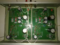
My build completed:
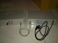
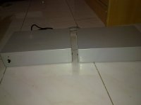
Pearl 2 boxed -

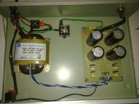
Dual unregulated 33V Power Supply -

Using 22-0-22, 30VA r-core CT transformer.
PS connected with umbilical 3 core shielded cord with chassis ground (mains earth ground) connected through shield of the cord. 3 cores carry +v, 0, and -ve of PS. PS Cord length is 3 Ft. Somehow I misplaced Ferrite bid to be placed on mains power cord.

Waiting for face plates.

Impression - Very silent, clean and rich. Gain is very much, output is near to CDP level.
Two things amazed me.
1. How there are lesser clicks and pops compared to another phono? This is simple class A, there is no filter apart from passive RIAA network. I think somehow other phono circuits make it to resonate and amplify where these are here to the actual quantity.
2. Subsonic roll-off. Some records used to move speaker cone with 1-2 time /sec. That was inaudible subsonic waves. I was forced to use damping brush of my Shure M97xe cart. Now they are reduced and I can play without damper brush of my MM phono cart.
Thanks Wayne and all of you wonderful people.
Pearl 2 boxed -

Dual unregulated 33V Power Supply -

Using 22-0-22, 30VA r-core CT transformer.
PS connected with umbilical 3 core shielded cord with chassis ground (mains earth ground) connected through shield of the cord. 3 cores carry +v, 0, and -ve of PS. PS Cord length is 3 Ft. Somehow I misplaced Ferrite bid to be placed on mains power cord.

Waiting for face plates.

Impression - Very silent, clean and rich. Gain is very much, output is near to CDP level.
Two things amazed me.
1. How there are lesser clicks and pops compared to another phono? This is simple class A, there is no filter apart from passive RIAA network. I think somehow other phono circuits make it to resonate and amplify where these are here to the actual quantity.
2. Subsonic roll-off. Some records used to move speaker cone with 1-2 time /sec. That was inaudible subsonic waves. I was forced to use damping brush of my Shure M97xe cart. Now they are reduced and I can play without damper brush of my MM phono cart.
Thanks Wayne and all of you wonderful people.
Last edited:
Thanks! I read on this forum to exclude C7 - that's all. Only problem I faced was - settling 0 mv at output test pad where it was varying between +10 to -10mV within 30sec duration. Still worked fine. I kept it as is because though inputs were shorted still boxes were open for adjustment.Wonderful! Congratulations on a beautiful construction!
Did you have any issues during building?
Thanks, R-core transformer is built by local exporter from Hyderabad India whose name is written there. That guy saved my money by avoiding label print cost too. It cost little under $10 USD each for batch of 10 pieces.@omishra a very nice build.
From where did you obtain the R core transformer?
Now waiting for wooden faceplates and some heatsink to regulators, they are more than warm.
Those rectifier diodes are MUR860.
Very nice build. I'm thinking of building a phono stage too. Problem is, I don't own a turntable
Make your own table.
Thanks! I read on this forum to exclude C7 - that's all. Only problem I faced was - settling 0 mv at output test pad where it was varying between +10 to -10mV within 30sec duration. Still worked fine. I kept it as is because though inputs were shorted still boxes were open for adjustment.
+/- 10mV is very good. Mine sometimes runs away to + or - 60 to 80mV. Most of the time it is between +/- 20mV though. This is with the inputs open.
Problem is, I don't own a turntable or any records.
That's nothing that an application of proper funding can't fix...
Red vs Yellow Led
the voltage across the led sets the bias of the stages, so yes it would matter. Not harmful bad, but it changes the bias of your output stage, which he, Wayne, designed to be 1.7v or really close. mine is close to 1.8 and it sounds like heaven, so maybe if you listen then change you could see which you like.
Bias does change the sound in my experience. Hope I helped. enjoy
John
Having measured literally thousands of red LED's, I have never found any under 1,8V...
Arne K
Okay - then maybe there's not much sense to desolder the yellow LED from my board

Can anyone possibly give their wisdom on this matter?
Last edited:
Having measured literally thousands of red LED's, I have never found any under 1,8V...
Can anyone please document what type-no that is close to 1,7V?
AND where to get them???
Arne K
Filtering for "red" and forward voltage "1.7V" leaves 271 parts in the Digikey category LED Indication-discrete. Quite a few of them are normal axial types and in stock.
BTW I have Panasonic part P605-ND (Digikey) in mine with a forward voltage of 1.8. Never crossed my mind to match them. What happens if the bias is a bit higher? Higher gain? Measured voltage drop is between 1.6 and 1.7V, so I guess I'm OK.
Last edited:
- Home
- Amplifiers
- Pass Labs
- Pearl Two