Hi Mooly
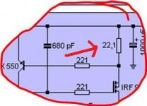
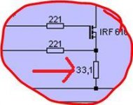
There is both a set of 22,1 ohm and a set of 33,1 ohm - but in each half of the circuit is also a 3,3 ohm, which is the first resistor after the DC input.
Thank you very much for your time!
Kind regards
Hans
") Sorry for keep asking but this could be why it's drawing excess current.
Sorry for keep asking but this could be why it's drawing excess current.What is a 22,1 ohm ???? and a 33,1 ohm. They are not recognised ways of writing the value of a resistor
You see at the input a 3,32K What's that ??
For example a 3300 ohm is normally written 3.3K or 3K3 or, (just to confuse things) may be marked on an actual resistor (SMD part) as 332 meaning 33 and two zero's.
You have to be very sure of the original designs values and what you have fitted.
Can you measure them on your meter ?
Is it 2.2 ohm ?
or 22 ohm ?
or 220 ohm ?
and same for the 33
I would concentrate on getting one side of the circuit to work first so that means removing say the right hand 22 ohm and ZTX550. That will isolate that side.
Attachments
Hi Mooly
They are 22.1 (twenty-two-point-one) and 33.1 ohm resistors. And a 3.3 (three point three) ohm at the DC input - Guess Kristjan K did not use the official notaion when doing this schematic. I have attached a portion of the official schematic that shows the same resistors. To me it looks like that the PS traces are seperate between channels, so I just connect one side at a time.
They are 22.1 (twenty-two-point-one) and 33.1 ohm resistors. And a 3.3 (three point three) ohm at the DC input - Guess Kristjan K did not use the official notaion when doing this schematic. I have attached a portion of the official schematic that shows the same resistors. To me it looks like that the PS traces are seperate between channels, so I just connect one side at a time.
Attachments
OK... so it works out like this,
PSU 60 Volt ac transformer gives around 85 volts DC input to the reg. 7 times 9.1v zeners is 63 volts less the gate source drop across the FET in the PSU, say 4 or 5 volts. So the PSU gives 60 volts or so output with 25 dropped across the FET (85-60)
The amp has a 33.1 ohms resistor as the element that defines the current flow in one side. The ZTX transistor turn on at around 0.7 volts B-E and holds the current in the chain constant. So the current is 0.7/33.1 = 22 ma. That gives a dissipation in the PSU FET of 0.55 watt or 1.1 watt both sides running. So yes a small heatsink should be OK.
So you have to now get one side to run OK, and that means totally removing the ZTX500 and the 22.1 ohm on one side only and also one of the 100 ohm that go to the preset pot.
The side that's left "should" power up and run with 0.7 volts across the 22.1 and 33.1 resistors.
I would definitely use a low wattage bulb in the PSU primary and have the meter connected across the 22.1 ohm as you power up. If the voltage goes over 0.7 switch off immediately and then you have to get technical with faultfinding on it easy...
PSU 60 Volt ac transformer gives around 85 volts DC input to the reg. 7 times 9.1v zeners is 63 volts less the gate source drop across the FET in the PSU, say 4 or 5 volts. So the PSU gives 60 volts or so output with 25 dropped across the FET (85-60)
The amp has a 33.1 ohms resistor as the element that defines the current flow in one side. The ZTX transistor turn on at around 0.7 volts B-E and holds the current in the chain constant. So the current is 0.7/33.1 = 22 ma. That gives a dissipation in the PSU FET of 0.55 watt or 1.1 watt both sides running. So yes a small heatsink should be OK.
So you have to now get one side to run OK, and that means totally removing the ZTX500 and the 22.1 ohm on one side only and also one of the 100 ohm that go to the preset pot.
The side that's left "should" power up and run with 0.7 volts across the 22.1 and 33.1 resistors.
I would definitely use a low wattage bulb in the PSU primary and have the meter connected across the 22.1 ohm as you power up. If the voltage goes over 0.7 switch off immediately and then you have to get technical with faultfinding on it
easy...
Last edited:
Success....
Thought I would do a small update on this problem - I changed all the semiconductors, and (of course) the thing started working. What it was exactly I do not know - but something got toasted probably when the PSU caught flames initially....
Now I just have to experiment a little with the input pad settings, and some wireing - I have more buzz than I like. As of now, all ground wireing meet at a star ground: input rca, output rca, attenuator, pcb signal in and pcb signal out. Think this is the best way - is it not?
BTW - it sounds really good I think - noticeable better than my stock Balanced Zen Linestage. Most noticeble the highs have more detail, and the sound seems to have more transperency - understood as I can hear more details on instruments that are in the background of the mix/sound image....
Thank you for the help and assistance!
Kind regards
Hans
Last edited:
- Status
- This old topic is closed. If you want to reopen this topic, contact a moderator using the "Report Post" button.