Hi Guys,
I would like to report some success. I had been toying with this idea of using a B1 for active crossover using Sallen-key filters for over an year, but some how never got around to building it. Finally I built one channel P to P on a proto board. Th improvement in sound quality over my passively crossed over speakers are huge. However, building it P-P is just too much work and a big challenge. Not recommended for noobs.
The sound is so much more fuller and rich. The notes well defined, you can sense the separation between instruments so well. My son can't wait for me to get the other channel finished.
Dave (Planet-10),
You really should give this a try, it might change your mind about Sallen-key filters.
Regards,
Dinesh
Dinesh,
I can't wait for you to get the other channel finished, either...
") Any chance of more info/photos/listening impressions???
Any chance of more info/photos/listening impressions???AndrewT,
I only just noticed that our last posts crossed.... I'm going to do a slight variant of what you suggested - will post and tell if it works...
Cheers
Nigel
Nigel, allthough simple by its self, the preamp you chose (after x-over) is very demanding when it comes to PS (almost no PSRR for +U and worse than that for -U). If you want optimal results, use suggested shunt reg, at least for -4.6V
Thanks juma, acutally I am planning on using essentially the same circuit from post #23 on your BF862 preamp thread (if this isn't the one you mean please let me know...).
The only differences are the following: I am using one transformer to power everything including filters and output buffers. Trafo is centretapped 24 - CT - 24, one regulator, will give me about +/- 33 Vdc unregulated and unsmoothed. Pair of 2200uF electrolytics (with 0.47uF snubbers do preliminary smoothing. This will then run the +ve regulator of your circuit, giving the +24.65 V needed, and a pair of preliminary regulators 7815/7915 (probably with a 7824/7924 pair before them, to share the heat issue). This pair gives +/- 15V which will then be regulated further by two regulator circuits: one is the -ve part of your circuit which gives -4.6V, and the other is the symmetrical regulator from the "symmetrical B1 buffer" thread, which will give me +/- 8 to 9 V to run the filters. This gives a slight lack of symmetry, since the current draw from the 7915 will be a little higher than from the 7815, but I don't think it's enough to matter. (??)
If anything looks odd or a bad idea please let me know - I'm off to buy more parts after lunch!
Cheers
Nigel
why are you running the filters from +-9Vdc?
I will be using BF862 in place of 2SK170. Reducing voltages to +/- 9V (more or less) was suggested by Jacques above (post #43), since BF862 has a lower absolute max voltage. Seemed prudent, so I'm planning on doing it.
Cheers
Nigel
Last edited:
Nigel, +/-9V for x-over is a good idea - not just because of Vds max, the dominant criteria is Pd max. They'll be working on Idss (about 13mA) x 9V = about 120mW which is OK for such a tiny part. More than that and worries about temp. drift will start - remember your last project with BF862
Nigel, +/-9V for x-over is a good idea - not just because of Vds max, the dominant criteria is Pd max. They'll be working on Idss (about 13mA) x 9V = about 120mW which is OK for such a tiny part. More than that and worries about temp. drift will start - remember your last project with BF862
Oh, don't worry I remember well....
In fact, the amp is doing daily duty, and performing very well indeed - I'm very pleased with it. Let's hope the experience building it helps here..... Cheers
Nigel
Dinesh,
I can't wait for you to get the other channel finished, either...
Nigel
Nigel,
Here goes. I have 4 stages of "B1" configured as Buffer->Stepped Attenuator->Buffer->LP & HP Filters
PSU is nothing special, just vanilla LM317/337 regulators supplying +/- 9V.
As far as impressions are concerned, give me a few days and my second amp will probably be done, then I can run one speaker active and another passive. As already mentioned, this is definitely the way to go, compared to passive crossovers. The sound is much more fuller, and clean, not to mention much more dynamic and punchy.
Attachments
Hi Dinesh,
I'm most interested to hear your impressions. Can I ask a couple of stupid questions?
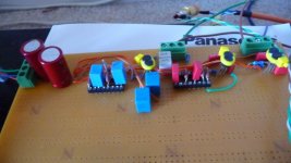
In the photo I can see three jfets pairs on the board; are these the parts after the attenuator? I guess you have the earlier Buffer in your list as
part of some different board. (Maybe in a preamp?) In any event, you are doing the 12db/octave original version, right?
I'll be very interested to hear how it sounds. How are you planning to fit this into your system? I'm being nosy - what crossover point, amps, speakers et cetera.... Do you plan on doing a more sophisticated PSU later?
My build is proceeding OK. I have a habit of always building the PSU first, and in this case I plan on getting the output buffers working next, to give a functional BF862 preamp, then do the filter section last. So it'll be a while before I can hear how it sounds....
Cheers,
Nigel
I'm most interested to hear your impressions. Can I ask a couple of stupid questions?
Nigel,
Here goes. I have 4 stages of "B1" configured as Buffer->Stepped Attenuator->Buffer->LP & HP Filters
In the photo I can see three jfets pairs on the board; are these the parts after the attenuator? I guess you have the earlier Buffer in your list as
part of some different board. (Maybe in a preamp?) In any event, you are doing the 12db/octave original version, right?
As far as impressions are concerned, give me a few days and my second amp will probably be done, then I can run one speaker active and another passive. As already mentioned, this is definitely the way to go, compared to passive crossovers. The sound is much more fuller, and clean, not to mention much more dynamic and punchy.
I'll be very interested to hear how it sounds. How are you planning to fit this into your system? I'm being nosy - what crossover point, amps, speakers et cetera....
Do you plan on doing a more sophisticated PSU later?My build is proceeding OK. I have a habit of always building the PSU first, and in this case I plan on getting the output buffers working next, to give a functional BF862 preamp, then do the filter section last. So it'll be a while before I can hear how it sounds....
Cheers,
Nigel
Based on my experience with pre-amps and phono-amps, when the design of the functional part is good most critical is the PSU. I agree with Nigel's PSU first.
I think Salas sym PSU B1 is a very interesting option. Does someone have a clue how many buffers, filter-stages, one could hook up to that specific B-1 design?
Regards
Michiel
I think Salas sym PSU B1 is a very interesting option. Does someone have a clue how many buffers, filter-stages, one could hook up to that specific B-1 design?
Regards
Michiel
Based on my experience with pre-amps and phono-amps, when the design of the functional part is good most critical is the PSU. I agree with Nigel's PSU first.
I think Salas sym PSU B1 is a very interesting option. Does someone have a clue how many buffers, filter-stages, one could hook up to that specific B-1 design?
Regards
Michiel
Hi Michiel,
I'm using separate regulator circuits for the filters (which will be essentially the Salas circuit from the sym B1 thread) and for the output buffers, which are the ones from juma's BF862 preamp thread. I'm hoping (and expecting) one salas PSU is enough for the filters - if anyone thinks otherwise please let me know while there's still time to adjust the design...
Cheers
Nigel
I would be tempted to use a separate pair of regulators for each channel.
Then I would consider using separate regulators for the upper frequency range from the lower frequency range. The input buffer could be run off the lower frequency range.
That's 4 pairs of regulators for a stereo crossover.
Then I would consider using separate regulators for the upper frequency range from the lower frequency range. The input buffer could be run off the lower frequency range.
That's 4 pairs of regulators for a stereo crossover.
I would be tempted to use a separate pair of regulators for each channel.
Then I would consider using separate regulators for the upper frequency range from the lower frequency range. The input buffer could be run off the lower frequency range.
That's 4 pairs of regulators for a stereo crossover.
Hmmmm... Did you mean four pairs of 7809/7909 regulators, or four pairs of discrete regulator circuits? I'm planning on using the sym B1 discrete regulator circuits; each pair of these uses: 2 IRFP9240, 2 IRFP240, 6 2SK170, 1 BC550, 1 BC560, and 16 LEDs. I don't think doing four of these is really practical in the space I have available. Total heat would probably not be much different from powering it all one from one pair, although I'm almost tempted just to see what 64 LEDs in one case would look like...
) It *might* be possible to fish around for a slightly simpler circuit to use instead, but it isn't clear to me if the benefits of having separate circuits outweigh the disadvantages of a simpler circuit...Cheers
Nigel
I had almost finished a reply when the power went out for a couple of minutes, and internet service took ages to come back... Annoying as all hell; on the other hand every time I moan about bad aspects of life in Brazil I should reflect on the fact that here today it is warm and sunny with a mild breeze, just about perfect (as it is most days, really...), whereas AndrewT and everyone else in the UK has rather different weather.... 
A total of 14. This includes 4 on the output buffers, which have entirely separate regulator circuits, and a total of 10 in the filters, being 1 input buffer and two buffers each in LP and HP, per channel. The BF862s will be running at Idss, about 13mA each, so total current draw in the filters should be about 130mA, which seems to me to be more or less OK with just one pair of regulators, if I heatsink the mosfets well. (If anyone thinks not, please let me know.) This is from a purely electrical point of view, however; if sonically this might be a little too much by raising the noise levels then I could adapt this, maybe, but I'd like to hear suggestions in this case.
Cheers
Nigel
builders are reporting very good SQ results for B1s on discrete shunt regulators.
Most are hanging only two B1s on one pair of regulators.
How many B1s will your crossover have?
A total of 14. This includes 4 on the output buffers, which have entirely separate regulator circuits, and a total of 10 in the filters, being 1 input buffer and two buffers each in LP and HP, per channel. The BF862s will be running at Idss, about 13mA each, so total current draw in the filters should be about 130mA, which seems to me to be more or less OK with just one pair of regulators, if I heatsink the mosfets well. (If anyone thinks not, please let me know.) This is from a purely electrical point of view, however; if sonically this might be a little too much by raising the noise levels then I could adapt this, maybe, but I'd like to hear suggestions in this case.
Cheers
Nigel
Its been too busy with my day job lately.Hi Dinesh,
In the photo I can see three jfets pairs on the board; are these the parts after the attenuator? I guess you have the earlier Buffer in your list as
part of some different board. (Maybe in a preamp?) In any event, you are doing the 12db/octave original version, right?
The picture shows only a part of the board. I started building the second channel, when the first buffer stage was finishedm out of curiosity I thought how would it sound if I bufferred the output from my Twisted Pear Sabre DAC before hitting the 10K stepped attenuator. The improvement was so much, I decided to leave it there, so I will add back another B1 stage into the channel shown.
The speakers are Eminence Alpha 15 and a Fostex FF85KeN in OB. The crossover point is not a Linkwitz-Riley, but actually spread apart a little bit. I am still playing with the components. It is very difficult to decide, because different crossover points bring out different characteristics. I am glad I put in that 16 pin DIP socket. Right now the tweeters are cutting in at 480Hz while the woofer is cutting out at 200Hz. Yes it is simple 12 db/octave filters. These are driving a Pavek Dudel's PA-03 amp based on LM4780, it was a GB right here at DIYA.I'll be very interested to hear how it sounds. How are you planning to fit this into your system? I'm being nosy - what crossover point, amps, speakers et cetera....
My build is proceeding OK. I have a habit of always building the PSU first, and in this case I plan on getting the output buffers working next, to give a functional BF862 preamp, then do the filter section last. So it'll be a while before I can hear how it sounds....
Cheers,
Nigel
I plan to build a shunt regulator later on, probably rebuild the whole thing on PCB. I will be housing it in an old cabinet, I have lying around from another project from a couple of years back.
Sound wise, the first thing the strikes you is that the sound stage moved forward, like going from 15th row to something closer to the performance. Given that I do not yet have the second channel built, I cannot be too sure of this. The articulation improved a lot and so now I can play it at lower levels than I used to. Of course, last few days nothing is playing, because the power amp is getting a make over. I am adding a second board to the power amp so that I can drive 4 drivers independantly. Once the second PA-03 board is complete, I will get back to building the rest of the cross-over.
I am convinced that this is a very worthy project despite the effort it takes to build it P-P.
I would be a great thing to design a small PCB that can take 2 channels single filters. Then you can just use these as building blocks. One for buffer, one for LP, one for HP and on and on, just chaining them as needed. I don't have the software tools for PCB design, but we'll see.
Regards,
Dinesh
I think this project looks really interesting. I am toying with the discrete x-over idea myself, but you guys are way in front of me. After having played with an XVR1 at a delayed "after-party" to the burning amp festival I must say that I'm really into this way of doing speaker designs!
If you want me to, I would love to design a PCB for this B1 based crossover since I would probably be doing it anyway.
The XVR1 uses jumpers, which I find really nice when testing - you can select the frequency and Q. DIP switches can also be used and may be easier to work with. It does require a lot of different resistors, but you get a really versatile tool for future projects.
- Status
- This old topic is closed. If you want to reopen this topic, contact a moderator using the "Report Post" button.
- Home
- Amplifiers
- Pass Labs
- B1 Active Crossover