I don't have enough 2SK170's to build the crossover, would there any disadvantages in building the buffers with BF862 other than fiddeling with SMD.
I have been very successful builduing buffers with j310. I think on semi still produces them as TO-92.
Best regards
floric
Hi buzz and Floric, thank you for the replys.-------------------------------------------------------------------------------------------------------buzz, thanks for the reminder, I should be OK if I pick the ones with the lowest IDSS, I also have some nice little DIL heatsinks that should help to keep things cool.--------------------------------------------------------------------------------------------------------------------------------Floric, I was thinking of using J309's, but I'm going to use Rod Elliots Project 09 boards, it's uses opamps (yuck) so I need to build the buffers onto an 8 pin DIL header, smd seemed to be the answer, I may still go with the J309's if I can find 100 or so.-------------------------------------------------------Sorry about the --------- guys, I hate my work computer, it removes all the spaces and scrunches everything up.
Last edited:
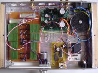
The final circuit is like the one I posted earlier, but with 221R gate stoppers at each and every gate. And one 2200uF 50V Panasonic FC capacitor per rail for decoupling and peace of mind.
To avoid potential ground loops, the XO's ground is only connected to the DCB1 at one point, namely through the cables coming from the power supply. Since the circuit is biased in class A I see no potential harm in doing so.
Dave, or anyone,
Other than these extra capacitors, does the stock DCB1 power supply need to be altered at all to keep up with the additional buffer circuits?
Looking into a similar build, but my power supply knowledge is lacking.
Hi harmolodics,
Before I had built the DCB1 crossover, I was using the hotrodded Salas DCB1 simply as a preamp (buffered volume control really). When I decided to build the crossover I simply used the DCB1 as a power supply for the circuit. For construction details you can check out my blog entry here at diyAudio: http://www.diyaudio.com/forums/blogs/rodeodave/509-my-salas-hotrodded-dcb1-build.html.
Like I mentioned in post #269 http://www.diyaudio.com/forums/pass-labs/156094-b1-active-crossover-6.html#post3435549, the only(!) modification I did to the previously built hotrodded DCB1 was the addition of a 5R1 resistor (10W wirewound iirc) in parallel to the previously installed 10R, effectively creating a 3R3 resistance in the DCB1's current source. The additional resistors are mounted on the underside of the board.
For current draw, simply assume 10mA per JFET pair, sum over all pairs and double or triple the result, depending on xformer and heatsink size, which are the only practical concerns more or less.
For instructions regarding setting up the Hypnotize DCB1 power supply, see http://www.diyaudio.com/forums/powe...notize-general-shunt-reg-pcb.html#post1952317.
Good luck, and keep us updated on your progress!
Last edited:
Thanks Dave! Those are very helpful links. My plan is to use the DCB1 plus 2 additional buffers to make a simple buffered line level crossover. So it might not be considered an "active crossover" like yours, but this way I can make the crossover parts modular so they can be easily swapped out for different values or slopes.
stepped attenuator - B1 < High Pass - B1
.....................................Low Pass - B1
With three JFET pairs per channel at 10mA per pair, I calculate the current draw to be 60mA, multiplied by 3 for headroom gives me 180mA CCS. Plugging this into Salas' equation (CCS=2.2/R) gives a resistor value of around 12R. Does this sound right?
Working on tracking down parts. Looking forward to biamping.
Last edited:
12R sounds about right. I've had around 150mA with 10R in my DCB1 build. As long as the transformer and the heatsinking can keep up, you can always increase the current.
Are you going for a buffered PLLXO as in TLS.org | Passive Line-Level Crossover ? I built a 12dB/oct version before I finished my B1XO, and it required quite some gain (delivered by BOZ) to make up for the PLLXO's insertion loss, but that was because my amps have a fairly low input impedance (22k and 15k). I can dig up the schematic if you want.
Are you going for a buffered PLLXO as in TLS.org | Passive Line-Level Crossover ? I built a 12dB/oct version before I finished my B1XO, and it required quite some gain (delivered by BOZ) to make up for the PLLXO's insertion loss, but that was because my amps have a fairly low input impedance (22k and 15k). I can dig up the schematic if you want.
I've just completed two B1 crossovers.
I have been following this thread for a couple of years, and I have now just completed
two LR4 crossovers based on this design for two of my systems.
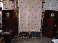
System 1. Lowther EX4 front horns with Jensen P15N in corner (rear) horn cabinets crossed over at 180Hz. Used Russian K71 100nF capacitors.
System 2. Fostex F120A in Voigt Pipes, with B&G Neo3PDR dipole tweeter crossed over at 1kHz.Used Russian K73 31nF capacitors.
I am very pleased with these XO solutions for both systems. I used straight forward
variable LM317/337 series regs for +/-10V rails.
I am now looking to build a 3 way version of this LR4 design for my "Orion"
variation of SL loudspeaker. I use cheaper drive units than what SL specifies, and have been using a Behringer DCX2496 as XO, emulating SL analog design in the digital domain. HP and MP should be straightforward with the B1 design ( I won't bother with the Notch Filters), but I'll need a shelving low pass for the bass open baffle drive units.
I don't know yet if the B1 non-inverting design can make a SLP, if not, I may use op-amps for the woofers only.
Any ideas?
Davidkou
I have been following this thread for a couple of years, and I have now just completed
two LR4 crossovers based on this design for two of my systems.
System 1. Lowther EX4 front horns with Jensen P15N in corner (rear) horn cabinets crossed over at 180Hz. Used Russian K71 100nF capacitors.
System 2. Fostex F120A in Voigt Pipes, with B&G Neo3PDR dipole tweeter crossed over at 1kHz.Used Russian K73 31nF capacitors.
I am very pleased with these XO solutions for both systems. I used straight forward
variable LM317/337 series regs for +/-10V rails.
I am now looking to build a 3 way version of this LR4 design for my "Orion"
variation of SL loudspeaker. I use cheaper drive units than what SL specifies, and have been using a Behringer DCX2496 as XO, emulating SL analog design in the digital domain. HP and MP should be straightforward with the B1 design ( I won't bother with the Notch Filters), but I'll need a shelving low pass for the bass open baffle drive units.
I don't know yet if the B1 non-inverting design can make a SLP, if not, I may use op-amps for the woofers only.
Any ideas?
Davidkou
Is the shelving low pass (slp?) a passive filter (EQ?)?
If so then all you need to get it to work correctly is for the filter to see the correct source impedance and to see the correct load impedance.
If those "correct" impedances are: zero for source and infinity for load, then use the B1 buffer for both input and output.
If so then all you need to get it to work correctly is for the filter to see the correct source impedance and to see the correct load impedance.
If those "correct" impedances are: zero for source and infinity for load, then use the B1 buffer for both input and output.
You could use a B1 buffered passive version with Active Filters and put it in front of the whole x-over. That's what I'm using for baffle step compensation in mine.
And post some pics please")
And post some pics please
For my "Orion" project, the Shelving Low Pass (SLP) is for open baffle dipole EQ, f1=20Hz, f2=300Hz Gain +10db in band, 0dB out of band, 6db/oct slope. This could be achieved well with a passive RC network, buffered by B1 stages as you have suggested. However, I think I might prefer an op-amp here so I can get a bit of gain an the same time. The woofer is crossed over at 100Hz with 24db/oct slope, so I think the op-amp will be ok for the woofer only, leaving the 2SK170 B1's for all the other work.
I have attached some photos of the Lowther Jensen system I mentioned (2 way, xo @ 180Hz LR4), incorporating IR remote volume control.
Thanks,
Davidkou.
I have attached some photos of the Lowther Jensen system I mentioned (2 way, xo @ 180Hz LR4), incorporating IR remote volume control.
Thanks,
Davidkou.
Attachments
SE B1 and other questions
I just finished reading this entire thread as it is exactly what I had in mind. I started with this thread: http://www.diyaudio.com/forums/analog-line-level/169005-jfet-active-crossover.html and thought "why not use a B1?" I have built a B1 and the improvement in my system was remarkable! But I have a few questions:
1) A few posts back, someone asked about using the original (SE) B1 schematic and I did not understand the answer as to why that is bad. I realize everything will be sitting @ 1/2 PS until the cap at the end, but is that a problem? I have the good fortune to have a 48VDC battery bank running my house (solar) so I have access to VERY CLEAN power supply. I'm sure I could just use a resistor voltage divider if necassary, but I do not understand the problem.
2) What is the issue with the extra buffer in the LP section? In the thread referenced above, that did not seem to be an issue, why here? With op amp versions an extra buffer is not used.
3) For those talking about using an IC socket for changing the freq, note that only the Rs need to be changed. The caps can be hard wired as long as you are not going to make huge changes in freq. That is how Marchand does it and I can say from experience that it workd well (though he does use 6 op amps per side and it is not a Snellen-Key network.)
Thanks for the help. I am anxious to try this.
If you need some (a little) adjust-ability in frequency, then it is usual to use a fixed set of accurately matched capacitors and replace the resistor bank. But the range of resistor values is quite limited by the circuit. This limits the range of adjustment.
If you want very big changes in frequency, then you must consider having banks of fixed accurately selected capacitors.
If you want very big changes in frequency, then you must consider having banks of fixed accurately selected capacitors.
I believe you missed something. I think that was discussed. I can take a stab at it. There is a Feed forward/back type of connection with a capacitor and the output node. The filter section really needs that node to be high impedance and connected to the output of a buffer, or an opamp, or an unknown load at the output, can load down the filter creating an out of band bump. The extra buffer if I remember, is connected to the input of the last buffer and forms a new output node, isolated from that section of the filter componentsI just finished reading this entire thread ...
2) What is the issue with the extra buffer in the LP section? In the thread referenced above, that did not seem to be an issue, why here? With op amp versions an extra buffer is not used...
Thanks for the help. I am anxious to try this.

If I read your graph right, the "problem" is @ -50dB and 10,000 Hz. Is that really a problem? I cannot imagine it being audible especially since it is being fed to the woofer which couldn't begin to reproduce a 10,000 Hz signal anyway. Could it cause more distortion? @ -50dB? I fail to see the real life problem that requires an extra stage as was eventually adopted. (I have read the entie thread.) But then again, I could be stupid or blind.maxlorenz and AndrewT,
Thanks for the good suggestions. At the moment, I am more concerned with dealing with the issue of the Sallen-Key topology where, for the low pass filter, the finite output impedance of the buffer in combination with the feedback capacitor provides a for a forward signal shunt path which manifests itself as poor stop band response. In this case and with these component values, the difficulties are well within the audio band. This can be addressed in a number of ways, so I am back to the drawing board to do some thinking....
Cheers,
Please enlighten me.
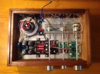
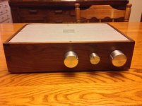
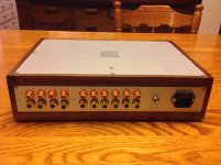
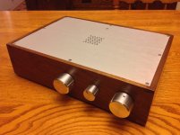
Just finished my DCB1 with a buffered 2-way crossover. Ready for some bi-amping! Don't have it hooked up to the system yet, but the test speakers sounded good. The crossover is on it's own board so it can be easily swapped out for different frequencies. Not the most elegant, but it should be reasonably flexible.
Attachments
Last edited:
 looks good!
 The crossover is on it's own board so it can be easily swapped out for different frequencies
Are the filter rates (attenuation slopes, frequencies, etc) for the high pass and low pass filters both the same or have you included any compensation for amplifier freq & phase response, driver differences, box diffraction, etc?
Is that block bridge with the 'Red Cap' across it a 'floating ground' mechanism?
You generally only need one adjustable volume on either output - suggest you try the high pass filter O/P without the series pot, if the low pass amplifier gain is high enough
- Status
- This old topic is closed. If you want to reopen this topic, contact a moderator using the "Report Post" button.
- Home
- Amplifiers
- Pass Labs
- B1 Active Crossover