If not using light bulbs, can we call it the Zen Ten?
Jajaja , nice name
Output Capacitor
In standard form, the ouput capacitor is sized at 10k uf, presumably
yielding a high-pass frequency in the single digits when used with
a nominal 8 ohm speaker. I'm considering assembling a stereo Delite
for some compression tweeters that are used with a passive
high-pass spec'ed to 1700hz. The first element in these 2nd
order high-pass filters is a 5 uf cap.
Is there any reason I could not put that cap in the amp in place
of the big electrolytic and connect the output to the coil that is
the parallel element in the crossover? I realize this would make it a
system-specific amp, but I am comfortable with this sort of thing.
Am I missing some impedance related issues that make this a
bad idea?
Thanks,
Skip
And it works
This looks familiar (my ZEN4). Would it be a worthwhile upgrade with the IXTH6N50D2 or would it be better to go for the power JFET (SJDP120R085)?
My idea is to drop the input buffer and biasing part completely and go for a Gate resistor of 47k and a source resistor...
Seems like nearly plug and play...
I tried the self biased R085 with a 1:1 OPT rather than the bulbs for a load. Needed about 2.5ohms source resistor with a +24V supply. Preferred the IXTH6N50D2 with 1ohm source resistor. Haven't tried bypassing the source resistor with the R085, that's a lot of uF ;-)
May try the R100 in there though....
Roscoe
May try the R100 in there though....
Roscoe
Dual Rail De-Lite
Hey guys,
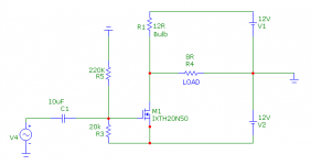
I've been putting together a dual rail power supply version of the De-Lite. Same basic idea, same MOSFET even, but a +/- supply to eliminate the DC on the output. No cap or transformer needed on the output.
It's works pretty well so far using +/-12V and a 12V-27W automotive taillight.
Just wondering if anyone has a spice model of the IXTH20N50 MOSFET that would work in Microcap. It's the spice flavor I'm familiar with, so it would be handy for me. So far, I've haven't simulated it, just built it - but the sims might get me closer to my goals faster.
I think Nelson uses Microcap, right? Any chance for a IXTH20N50 model? I've searched but have not found. Thanks!
Hey guys,
I've been putting together a dual rail power supply version of the De-Lite. Same basic idea, same MOSFET even, but a +/- supply to eliminate the DC on the output. No cap or transformer needed on the output.
It's works pretty well so far using +/-12V and a 12V-27W automotive taillight.
Just wondering if anyone has a spice model of the IXTH20N50 MOSFET that would work in Microcap. It's the spice flavor I'm familiar with, so it would be handy for me. So far, I've haven't simulated it, just built it - but the sims might get me closer to my goals faster.
I think Nelson uses Microcap, right? Any chance for a IXTH20N50 model? I've searched but have not found. Thanks!
Yep, there ain't much to it. See below. 12V and 12R is what I've been working with to start, but getting about 2A current flow may be the sweet spot. My 12V 25W bulbs can do that, but they are bright!
The idea is simple - as long as the voltage drop is the same across the MOSFET and the resistor (or bulb) then the node between them is at 0V compared to ground. Apply an AC signal and that 0V will fluctuate up and down. Voila - you've got an amp. To get the depletion mode MOSFET to drop the same voltage as the resistor/lamp, you have to turn it off a little. You want it to be the same resistance as the lamp. About 1V does it in this case.
There are some problems with this, but will go into that later, if anyone cares.
Attachments
Sure, you could use other MOSFETs. They don't even have to be depletion mode, they just have to be biased properly to drop the same voltage as the resistor or bulb.
One problem I'm finding is thermal - it takes some time to settle. Until the temperature settles, the DC offset drifts. That's not good for the speaker. The amp will probably need some sort of DC servo or DC protection circuit - and that's going to be about 5X more complicated than the amp. We shall see.
One problem I'm finding is thermal - it takes some time to settle. Until the temperature settles, the DC offset drifts. That's not good for the speaker. The amp will probably need some sort of DC servo or DC protection circuit - and that's going to be about 5X more complicated than the amp. We shall see.
I finally got back to this after a busy year. Now trying with Nichrome wire in place of the light bulb. I'm attempting a low voltage version.
These IXTH20N50 sure do seem to need a lot of bias current to get any decent voltage swing. As anyone else found the sweet spot for bias?
These IXTH20N50 sure do seem to need a lot of bias current to get any decent voltage swing. As anyone else found the sweet spot for bias?
Pano - I really need to come up and audition some of your stuff and take a look at your delite amp. I keep coming back and looking at this amp as a future build (too many project right now).
In any case, since I have nothing really to add to this thread - Good luck!
Ben K.
In any case, since I have nothing really to add to this thread - Good luck!
Ben K.
DELITE improvements
Here is my small contribution: a new connection of C3, the speaker and the 0V terminal. This allows a great improvement in the ripple rejection, without altering any of the other sound settings.

The improvement depends on the current and voltage of the circuit. The improvement also strongly depends on the resistance of the filament of the bulb.
Another thing I found is that if you choose a filament resistance equal to about twice the lower speaker impedance, frequency response is much flatter and pleasant. The impedance of a speaker tends to fluctuate between a minimum and a maximum value typically about 400 to 500%. Choosing a filament resistance equal to twice the minimum expected impedance value, ensures that the power dissipation in the speaker minimally varies between extreme frequencies of the spectrum.
I give an example: if the speaker impedance varies between 4 ohms and 16 ohms (between a frequency close to fs and about 10 KHz or more) and choose Rfilament = 8 ohms: Power at minimum impedance (about 200 to 600 Hz ) is only 0.51 dB greater than the power in a high impedance (near fs and 10 KHz or more).
Unfortunately this leads to a lower efficiency and less control of the low end of the frequency.
regards
PD: Check the polarity of the capacitor C4 (depending on how you connect your preamplifier). R1 can be changed to the opposite side, if you want. The 0V connection can be left as in the original scheme, if you want, too.
Here is my small contribution: a new connection of C3, the speaker and the 0V terminal. This allows a great improvement in the ripple rejection, without altering any of the other sound settings.
The improvement depends on the current and voltage of the circuit. The improvement also strongly depends on the resistance of the filament of the bulb.
Another thing I found is that if you choose a filament resistance equal to about twice the lower speaker impedance, frequency response is much flatter and pleasant. The impedance of a speaker tends to fluctuate between a minimum and a maximum value typically about 400 to 500%. Choosing a filament resistance equal to twice the minimum expected impedance value, ensures that the power dissipation in the speaker minimally varies between extreme frequencies of the spectrum.
I give an example: if the speaker impedance varies between 4 ohms and 16 ohms (between a frequency close to fs and about 10 KHz or more) and choose Rfilament = 8 ohms: Power at minimum impedance (about 200 to 600 Hz ) is only 0.51 dB greater than the power in a high impedance (near fs and 10 KHz or more).
Unfortunately this leads to a lower efficiency and less control of the low end of the frequency.
regards
PD: Check the polarity of the capacitor C4 (depending on how you connect your preamplifier). R1 can be changed to the opposite side, if you want. The 0V connection can be left as in the original scheme, if you want, too.
Attachments
Last edited:
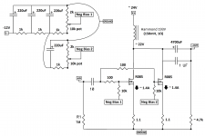
Soon when my R085 arrive (Thanks Tea-Bag!) I'll start building this little amp:
First I thought to use a single device per channel which should net me about 8-10 W into 8 ohm. I remember Nelson talking about that he likes to use these devices at 20-30W and since I will have enough JFETs for it I thought I could parallel two and do this:
Now I just need a sanity check if there is something dumb in the schematic =)
If I've understood correctly the degeneration works as output resistors so I won't have to add extra series resistance. My question is if there is any problems of both JFETs sharing the same current source which in my case is the big 193V inductor.
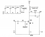
If this proves to be a bad idea then the plan is to use a single device like the second pic.
In the end the idea is to do 2x paralleled amps for the mids and then 2x single device amps for the tweeters, and those amps will have smaller inductors =)
EDIT: Though when you think about it's probably easier to just use one and push it to 40-45 W. If in 3 years one of them fails I still have 2 spares and when those also fail there will probably be a newer and more shiny transistor to use instead =)
First I thought to use a single device per channel which should net me about 8-10 W into 8 ohm. I remember Nelson talking about that he likes to use these devices at 20-30W and since I will have enough JFETs for it I thought I could parallel two and do this:
Now I just need a sanity check if there is something dumb in the schematic =)
If I've understood correctly the degeneration works as output resistors so I won't have to add extra series resistance. My question is if there is any problems of both JFETs sharing the same current source which in my case is the big 193V inductor.
If this proves to be a bad idea then the plan is to use a single device like the second pic.
In the end the idea is to do 2x paralleled amps for the mids and then 2x single device amps for the tweeters, and those amps will have smaller inductors =)
EDIT: Though when you think about it's probably easier to just use one and push it to 40-45 W. If in 3 years one of them fails I still have 2 spares and when those also fail there will probably be a newer and more shiny transistor to use instead =)
Attachments
Last edited:
Hmm, I think the 10k resistor & bias should be on the left side of the gate stopper resistor and not on the right. And when I think about it: As the R085s aren't perfectly matched then shouldn't it be better to have a cap to each of them so the bias of one can't leak onto the other one?
Last edited:
1) Naaah, it's fine.
2) Naaah, it's fine.
You can do it either way.
Nice!
Another thing I've wondered about dissipation and reliability:
If we take say the R085 or similar device and push it to 40-45W with generous heat sinking. Is it that you expect it to fail after say 5 years or is it that if you produce 100 amplifiers you expect a few of them to fail after say 5 years?
EDIT: I think I found you clarifying that a while ago: I take it this is true today too?
Last edited:
- Home
- Amplifiers
- Pass Labs
- Pass "DeLite" Amp from BAF