hi all
im running a aleph 5 with double the output devices so 12 per channel instead of 6 and i,m running a 500va 30/0/30 toroid per channel instead of the normal aleph 5 voltage of 28/0/28
is this ok or do i need more voltage like 40/0/40 to run the extra output devices
also what is the resistor that controls the bias on the brian gt mini a boards when they are built as a aleph 5
id like to up the bias as i,m running 4x conrad 350 x 151 sinks per mono block and have heaps of heat to spare
regards sheafer
You dont need higher voltage.
4 conrad heatsinks per channel should easily dissipate 400 watts of heat per channel.
So you are looking at about +/- 40V dc and 5 Amps bias current.
If you want to do this then using Nelson's formula (2:1 ratio) you need an 800VA transformer per channel.
You may as well go the whole hog and go for 1.5kVA transformer per channel.
I always love to hear of realy ambitious people.
Last edited:
You dont need higher voltage.
4 conrad heatsinks per channel should easily dissipate 400 watts of heat per channel.
So you are looking at about +/- 40V dc and 5 Amps bias current.
If you want to do this then using Nelson's formula (2:1 ratio) you need an 800VA transformer per channel.
You may as well go the whole hog and go for 1.5kVA transformer per channel.
Yep ...
Fully agree no substitute for cubic inches ...................

hi all
so am i correct in saying that if i double the outputs on the aleph 5 from 6 to 12 per channel (which i have) i can run the standard aleph 5 rail voltage no probs but the va rating of the transformer must be increased to supply the extra current ?
the 40vdc you refer to is this about what i will get after the powersupply and rectification using the 30/0/30 v ac voltage ?
im using a aussie amplifiers psu 3 powersupply per channel with 6x 18,000mf each
regards sheafer
Without doing any math, you should probably double the capacitance of the PS.
R13 on the Mini A attenuates the bias current, leaving it out will get you the junction voltage of Q5 across the source Rs so increasing the value above the A5 value will increase the bias. Don't go too far.
Check out the A60.
Best, Bill
R13 on the Mini A attenuates the bias current, leaving it out will get you the junction voltage of Q5 across the source Rs so increasing the value above the A5 value will increase the bias. Don't go too far.
Check out the A60.
Best, Bill
Last edited:
hi guys
great so i understand (i think)
now re the capacitance ,so are you saying that the 108,000mf per rail i have is not enough ? i thought it would be fine
jeez looks like im going to need a chassis just for the caps themselves
re the toroid i cant find 30,0,30vac toroids in over 500va so im stuck there
i do have 2x 1kva 40/0/40 toroids but the voltage is too high too use unless i could cut it down to 30/0/30 somehow
hi bill so all i have too do to increase the bias is leave r13 out ?
regards sheafer
500VA 30-0-30Vac transformer has a maximum continuous DC output current of ~4Adc, after the rectifier and smoothing. You cannot and should not ask for 5Adc bias for a ClassA amplifier.
It is usually recommended that the operational continuous DC current be limited to less than or equal to half the maximum continuous.
A 1200VA 30-0-30Vac transformer can just meet this 5Adc bias requirement.
Is Pass' advice to use a transformer that is rated @ 6 to 10times the maximum output power?
It is usually recommended that the operational continuous DC current be limited to less than or equal to half the maximum continuous.
A 1200VA 30-0-30Vac transformer can just meet this 5Adc bias requirement.
Is Pass' advice to use a transformer that is rated @ 6 to 10times the maximum output power?
hi andrewt
so if i did run the 2x 500va 30/0/30/
with the above setup then what is the max bias i could run and be safe ?
or is the 2x 500va totaly unsuitable for this project
if i run higher power supply capacitance then can the va rating of the toroid be relaxed a little so that the 500va is ok
also i can get a the same 500va toroids in 25/0/25 if needed so im thinking by lowering the supply voltage a little i could still run a high bias with the 12x irfp240 per channel and stay safe with the 500va toroids
id love to be able to get some 25/0/25 in 1kva for the project but there is just nothinbg available in that voltage over 500va in australia
your oppinions are aleays appreciated
regards sheafer
then buy 50-0, 50-0 1kVA........to be able to get some 25/0/25 in 1kva
take each output winding and half it to get four secondaries of 25-0.
Now you can parallel pairs of windings to get 1kVA 25-0, 25-0 with a rating of 5Adc continuous after applying the <=50% de-rating for cool running duty.
Even better, rectify each winding and then parallel them to keep the heat dissipation in the rectifiers lower.
hi guys
great so i understand (i think)
now re the capacitance ,so are you saying that the 108,000mf per rail i have is not enough ? i thought it would be fine
jeez looks like im going to need a chassis just for the caps themselves
re the toroid i cant find 30,0,30vac toroids in over 500va so im stuck there
i do have 2x 1kva 40/0/40 toroids but the voltage is too high too use unless i could cut it down to 30/0/30 somehow
hi bill so all i have too do to increase the bias is leave r13 out ?
regards sheafer
I never considered trying that, it will probably change the % of current contribution from the current source. Try replacing with a 500K trimmer set at 220K then slowly increase it watching the source R voltage drop. Alternatively you could lower all the source Rs. Just be aware you are deviating from the design parameters.
id love to be able to get some 25/0/25 in 1kva for the project but there is just nothinbg available in that voltage over 500va in australia
your oppinions are aleays appreciated
regards sheafer
You can get any voltage and any va rating from this guy Manufacturer of toroidal TRANSFORMERS-Home page
And they are of top quality, and excellent price. I highly recommend them.
hi all
sorry andrew
i re read your post and you did make it clear
instead of buying more toroids what can i do to make my 1kva 40/0/40 toroids work ?
how can i drop the voltage down to 30/0/30
is there a reg i can make or buy that could handle the current or perhaps unwind some of the secondry,s (not my prefered option if possible)to get the voltage i want
ive got enough heatsink to just run the 40/0/40 voltage but this would mean running less bias
from what i understand it would sound better if i run a lower voltage and bias the hell out of it or am i way off here
regards sheafer
how can i drop the voltage down to 30/0/30
You've been asking the same question for some time now; are you expecting a different answer? The simplest i.e. cheapest way to do this is via CRCRC type PSU. Just use big resistors. Or, in lieu of all that, you can use a variac.
Last edited:
hi all
thanks andrewt
i will open her up and check it out tonight
it would be great if i could use them as the were very expensive
hi megaamp
i realise the simplest way may be the psu you suggested but i already have 2x aussie amps psu with 108,000mf each and they are very good
so i would be wasting money not using them
regards sheafer
hi guys
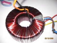
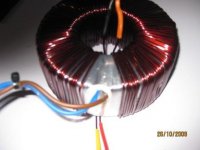
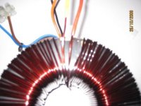
heres some pics of one of the toroids with its wrapping removed
i presume to lower the voltage from 40/0/40 to 30/0/30 i just have to unwind each secondary wire the same amount of turns untill i get the required voltage correct?
regards sheafer
oops forgot
the secondarys are single wire looks to be 2mm or more each
Attachments
Last edited:
2mm diameter wire is unusually thick for toroid windings.
It is just 3.1sq mm. That has a current density of ~4A/sq mm.
This density is a bit high.
What is the regulation of this 1kVA? 4% or 4.5%.
At a current density of ~3A/sq mm you would expect ~3.5% regulation for 1kVA.
If you remove turns from this transformer you will reduce the VA rating, making the regulation even worse.
- Status
- This old topic is closed. If you want to reopen this topic, contact a moderator using the "Report Post" button.
- Home
- Amplifiers
- Pass Labs
- aleph power questions