A better way of using a transformer(if this an option) and also get rid of coupling-caps is to place it between DAC and B1. As a good transformer like LL1690 has a Zout, in the ballpark, of 1k it is not the best to drive long cables. Let the B1 take care of the low Zout instead. Any additional filters can be placed differentially before or after the transformer. There may be need for additional loading on the transformer but that must be done by measuring and listening.
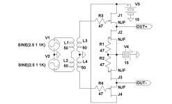
ERROR in the schematic V2 should be opposite phased.
ERROR in the schematic V2 should be opposite phased.
Attachments
Last edited:
OK, I could not resist the temptation.
Firstly I wonder what is new in this. My Sony XB940 has such a JFET Follower (a la Curl) output stage for 4 years.
As to the circuit proposed in #12. If I were to use split rails anyway, I would put the HP (i.e. decoupling cap) on the high impedance part, which means input. That saves you money on caps.
I would not use separate cap multipliers on the left & right side. Reason is simple. In a balanced circuit, the AC current draws are out of phase and compensates each other, so that the (common) power supply sees constant impedance. Using separate supplies makes it worse.
If you are really daring, you can float the entire DAC, use single rail, and BJTs for the lower current source (where 2.5V Vce is OK), and just run the outputs at 2.5V DC, which you may (or may not) ground to the rest of the equipment. This means that the DAC Ground is now effectively at about -2.5V relative to the system ground, but floating. Advantage ? No caps.
Matter of opinion of course. Mr. Choky would no doubt have a different one.
Merry Christmas,
Patrick
.
Last edited:
,,,,, Mr. Choky would no doubt have a different one.
Merry Christmas,
Patrick
.
yes and no ;
all roads leave to Rome .
Merry Christmas

Thanks a lot for all your input.
The hole point of running a buffer without gain is that this dac-chip already have enough voltage output(at least in my setup). At the moment I will stick with this thinking. But who knows what the future brings.
I have reread the B1 article, and will also try the Vishay caps Nelson uses.
The hole point of running a buffer without gain is that this dac-chip already have enough voltage output(at least in my setup). At the moment I will stick with this thinking. But who knows what the future brings.
I have reread the B1 article, and will also try the Vishay caps Nelson uses.
AR2 told me that his DAC is somewhat wimpy for driving xformer
For some reasons some funny people tries to adopt 600ohm transformers to voltage Dacs. This one is at least 10k at lowest frequency and is ideal for this purpose. The DAC can take down to 2ks without any problems.
For some reasons some funny people tries to adopt 600ohm transformers to voltage Dacs. This one is at least 10k at lowest frequency and is ideal for this purpose. The DAC can take down to 2ks without any problems.

yup - we all are learning every day ...... and fact that Lundahl are not so clear in their primary's impedance isn't helpful ...... at least for beginners
Agree about the lack of information.
I talked to Pär about inductance data on the small signal transformers but he didn´t want to say anything. He only publish them on the ITs and the OPTs. The 10k at 20Hz is the ballpark figure I got from Kevin with both windings in series.
I talked to Pär about inductance data on the small signal transformers but he didn´t want to say anything. He only publish them on the ITs and the OPTs. The 10k at 20Hz is the ballpark figure I got from Kevin with both windings in series.
Agree about the lack of information.
I talked to Pär about inductance data on the small signal transformers but he didn´t want to say anything. He only publish them on the ITs and the OPTs. The 10k at 20Hz is the ballpark figure I got from Kevin with both windings in series.
hehe
in case that you posted that on my local forum , you would be sentenced by now .....
our usual sentence is "go $uck o$$ to drink a beer , order one to me , too "
so - that's usual that beginner is advised to use LL1674 , even for voltage output DACs
not by me , just because I never advise anything which I didn't tried
For some reasons some funny people tries to adopt 600ohm transformers to voltage Dacs. This one is at least 10k at lowest frequency and is ideal for this purpose. The DAC can take down to 2ks without any problems.
There is some confusion about this specification. A "600" transformer does not mean that the transformer is presenting a 600 ohm load to the DAC. The transformer will have some resistance on its on, but it is a trivial amount. The transformer is reflecting the impedance of the next element in the chain. Of course, if the ratio of the windings is not 1:1, the impedance that is reflected will accordingly change. If the DAC needs a 2kOhm load, you can place resistors before the transformer (which you may want to do if you are setting up an RC anti-aliasing filter). Or this load can be from the next element in the chain (pre-amp, volume control etc).
As pointed out, one issue about using a nominal "600 or 10k" transformer is the inductance that will be presented. This can be quite different and unfortunately manufacturers do not always list this specification.
With...: If you read my text again you´ll see that I tried to discuss inductance of small signal transformers with Pär Lundahl. And very few other makers do. Dave Slagle is an exception and he make great transformers.
Often impedance is related to inductance at 20Hz but you can not be sure.
If you mean that one should place series resistors at primary it not a very good idea as you lose signal and also might lose dynamics(not all will agree).
Still what is commonly called 600:600 ohms transformers are normally not suited for voltage DACs due to their low inductance at low frequencies.
For some reasons some funny people tries to adopt 600ohm transformers to voltage Dacs. This one is at least 10k at lowest frequency and is ideal for this purpose. The DAC can take down to 2ks without any problems.
Just came across this funny thread. I guess that makes me well fit into it.
")
This configuration, AKM voltage out DAC >>>>> Lundahl 1674 transformer, was designed for me and recommended by Kevin from KK audio. 1674 transformer is 1+1 4+4 type and is wired as 1+1 2+2. Original configuration 1+1 4+4 is not recommended to be used in this circuit. So far is working great and I am still to hear anything that will match that when it comes to transparency. The project that Zen Mode and I are working on is to solve several issues mostly related to different gains that I need in my three way system and to see if we could improve on output circuit I have with DACs and Lundahls. I did some measurement long time ago and this passive circuit presented clear advantage vs. active with opamps. I am very interested in seeing what it will do with jFets, vs. passive.
This issue of inductance and impedance with DACs and transformers is very convoluted, and any exploration here would be greatly beneficial. For people that never heard this simple set up - in my case AK4396 >>>> Lundahl1674 >>> balanced out, I would suggest, please try it, it is quite amazing.
Hey AR2,
Think we met in the DCX2496 thread. LL1690, 1674 and 1676 are great transformers in the same family. It is totally impossible to wire the for 1674 1+1:2+2! Maybe 2+2 should be 4//4?
My personal favourite of the bunch is LL1676 that I run 2+2:1+1 (balanced to unbalanced) and still get enough output level and also quite low Zout.
Last edited:
input LPF: damping factor is too high (1.5)
@Zen Mod
Borbely's drawings are easier to read
http://www.borbelyaudio.com/pics/305borbely-new.pdf
@Zen Mod
Borbely's drawings are easier to read
http://www.borbelyaudio.com/pics/305borbely-new.pdf
- Status
- This old topic is closed. If you want to reopen this topic, contact a moderator using the "Report Post" button.
- Home
- Amplifiers
- Pass Labs
- VoltageDAC with B1 output buffer