I thought is a nice idea to set up a thread dedicated to amplifiers based on old so-called V-FETs from the 70-ties (and 80-ties maybe). Transistors made by NEC, Sony and Yamaha, and to my knowledge in amplifers from Hitachi/Lo-D, JVC, Sansui, Sony and Yamaha way back then.
We have now and then touched it in the First Watt J2 thread http://www.diyaudio.com/forums/showthread.php?t=151909&page=10.
I have not concluded whether the output shall be common-source or common-drain. But maybe some will do this and some that, for all I know.
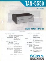
I found the Sony TAN-5550 service manual, I thought I had the TAN-8550 also, the one which is refereed to in the AES preprint I briefly flashed in another thread. But this one is good enough, just to show how a push-pull V-FET amp was built way back when..
Rolv-Karsten
We have now and then touched it in the First Watt J2 thread http://www.diyaudio.com/forums/showthread.php?t=151909&page=10.
I have not concluded whether the output shall be common-source or common-drain. But maybe some will do this and some that, for all I know.
I found the Sony TAN-5550 service manual, I thought I had the TAN-8550 also, the one which is refereed to in the AES preprint I briefly flashed in another thread. But this one is good enough, just to show how a push-pull V-FET amp was built way back when..
Rolv-Karsten
Attachments
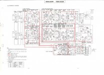
TAN-5550 circuit diagram
And here is the actual circuitry from the 1975 service manual of the Sony TAN-5550. This is decidedly class B.
I expect us to end up in class A, probably lower wattage, simpler circuit and all that.
RK
And here is the actual circuitry from the 1975 service manual of the Sony TAN-5550. This is decidedly class B.
I expect us to end up in class A, probably lower wattage, simpler circuit and all that.
RK
Attachments
The original Sony designs are a little odd - right around
that time we were starting to see some bold Class A
designs appear as concept pieces in Japan, and Stax
managed to get one into the U.S. marketplace.
One later Sony amplifier appears to have used these parts
to cascode its bipolar output stage - go figure.
My intent is to see what I can make of a complementary
pair of these as followers in Class A. As a concept it's easy
enough, we'll just have to see about the performance.
I haven't dug too deep into this, but I feel these amplifiers are overly complicated really. I wonder, in the AES preprint, these V-FETs are said to not have any extreme input capacitance, and should be easy enough to drive. There are several stages in cascade, open loop gain in excess of 80 dB.
I do not need hundreds ow Watts, I need some juice for ESL-63s. F5 would probably be enough for ESL-63 in most cases. So 20 - 60 Watts. And I do not think you need all those stages, but I guess you (NP) and others are in front of me thinking about this.
BTW I believe cascoding bipolars with V-FETs seems the opposite of what I would do
Maybe. I could easily write a whole article on this, addressing
the voltage and current relationships on a given part and
their contribution to performance, and then expand that to
a discussion of complementary versions of those parts in
push-pull.
Cascoding might be a better approach, but I haven't gotten
that far with these parts.
I will though...
the voltage and current relationships on a given part and
their contribution to performance, and then expand that to
a discussion of complementary versions of those parts in
push-pull.
Cascoding might be a better approach, but I haven't gotten
that far with these parts.
I will though...
One later Sony amplifier appears to have used these parts
to cascode its bipolar output stage - go figure.
Schematics of the Sony TA-N7 (TA-N7B, different color) are posted a few times in these forums. Here for example:
http://www.diyaudio.com/forums/showthread.php?t=106964
I have one of these and it's very good sounding, and highly sought after (it comes up once or twice a year on ebay and has been going for over $2000).
Steve.
Last edited:
R-K Rønningstad;1942321 said:Do you have datasheets from way back when?
Here's one for the 2SJ18's.
Steve
Attachments
The 2SJ28 has a pretty similar curve. You will note that
the Vds dependency is pretty linear, which will make for a
good opportunity for distortion cancellation - in a single
-ended circuit. Note that it is not exponential, that is to
say it is not a triode characteristic.
Either way, I think it remains to be seen how advantageous
this will be in a push-pull circuit.
Mr. Pass, any progress on the VFETs? You posted
somewhere that the graphs suggested these were
the closest things to triodes. Could you post your
graphs, especially the drain current variation with
gate voltage?
After reading your article, I'm inching to have a go
at these. Although, I don't have a distortion analyzer.
somewhere that the graphs suggested these were
the closest things to triodes. Could you post your
graphs, especially the drain current variation with
gate voltage?
After reading your article, I'm inching to have a go
at these. Although, I don't have a distortion analyzer.
I have received a surfeit of exotic devices lately, and it's
taking time to evaluate them properly.
Such a problem.
o tempora , o mores !
I'm always in same situation coming back from junkyard ......

From post #15: <<...especially the drain current variation with gate voltage?...>>
THAT measurment for SITs will be worthless. We need to be concerned with
the dynamic (in the presence of the real load) response: Vd=ƒ(Vg).
That can be determined from the actual (measured) curves Id=ƒ(Vd) with Vg
as a parameter (like those that you see in the datasheet) AND trying loadlines
for the different bias (Vd, Id, Vg) points to make shure, that you will get more
or less linear response. And things will get more complicated if your real load
is a speaker with its reactance.
If you don't have a Curve Tracer to perform those measurments, use simple
test setup, where you connect drain via power resistor to the power supply.
First, decide on a bias: Vd and Id.
For single SIT amp use resistor of the Load value (let's say 8-9 Ω).
For Push-Pull cl. A design case (two SITs) use resistor of the double
value (~16-18 Ω).
Calculate and adjust the necessary Power Supply voltage: Vs=Vd+R×Id
All Voltages must be of the appropriate polarity!
Connect Vg through the pot to the gate.
One Voltmeter goes to the Gate-Source, another to the Drain-Source.
Changing Vg (by the pot) tabulate the measured Vd versus Vg.
Plot the graph on the fine grid paper and decide if the response linearity
is acceptable.
SITs do have the optimal load value for minimum distortion.
- Status
- This old topic is closed. If you want to reopen this topic, contact a moderator using the "Report Post" button.
- Home
- Amplifiers
- Pass Labs
- Vintage V-FETs in class-A amplifier with complementary push-pull output