do not mix them ;
use same parts - if you can - in both halves
they are cheap enough anyway ...
regarding Fairchild parts - I'm not loosing my sleep about that issue
OK, thx. I'll see what I can get for a reasonable price.
Cheers
Nigel
Nelson, somewhere you remarked on a substitute by Harris, but without specifying a part number; are there other manufacturers out there with equivalent parts? ST or ON, maybe?
Harris parts are long gone, it seems.
Try Toshiba - 2Sj200 and 2SK1530.

..But what specifically makes the IRFP9240 a better choice than IRFP9140?
Slightly lower Crss and Coss, but as Zen Mod wrote - it's negligible, don't fret about it. I can only agree with him that even IRF9540/IRF9640 will do fine here
... I can only agree with him .......
what else ..... or you'll be sentenced by usual sentence .....

what else ..... or you'll be sentenced by usual sentence .....
Can I have a vine this time instead of beer (unless it's Pražský Staropramen or at least Velkopopovický Kozel)
Harris parts are long gone, it seems.
Try Toshiba - 2Sj200 and 2SK1530.
Slightly lower Crss and Coss, but as Zen Mod wrote - it's negligible, don't fret about it. I can only agree with him that even IRF9540/IRF9640 will do fine here
Thanks for all the help. I just pulled the trigger on a purchase through Farnell-Newark in SP. No Toshibas or 9240s, but the others were there with IRFP9140 at the best price, so that's what it will be!
Cheers
Nigel
Can I have a vine this time instead of beer (unless it's Pražský Staropramen or at least Velkopopovický Kozel)
I have no idea what that means, but if either of you find yourselves in Brasilia then the
 are on me!! Down here more likely to be beer or cachaca, although you can certainly have vine-products if that is your preference
 Um abraco (as they say down here...)
Nigel
I have no idea what that means, but if either of you find yourselves in Brasilia then the
Um abraco (as they say down here...)
Nigel
Juma and me - we are teasing one another ;
it's related to usual punishment on our local ( Serbian Diyaudio) forum, where most used penalty is "Marš na pivo!!" , meaning (probably impossible to translate ) "*uc* off & have a beer!!"

Juma and me - we are teasing one another ;
it's related to usual punishment on our local ( Serbian Diyaudio) forum, where most used penalty is "Marš na pivo!!" , meaning (probably impossible to translate ) "*uc* off & have a beer!!"
Aha!.. but nonetheless, the invitation stands!
Um abraco
Nigel
Hi,
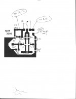
I have drawn out a plan for the (partial) PCB,and would be grateful for any comments.
If you remember from the discussion above, my plan is to use a small PCB containing all the BF862s, and with all surrounding resistors as SMD devices, which can be soldered into a larger protoboard with all the mosfet/high current stuff done p2p. I drew the file in GIMP and saved it as .pdf, but I couldn't manage to be clever and add the notations except by adding in hand and scanning ..... So here it is as a .jpg... Hope it's clear enough (and I'll happily post a clean .pdf once final version is ready if anyone cares.) The final board is for one channel (obviously) and should be square, about 2.5cm on each side. There are five or six points where there will be a pin connecting to the rest of the circuit.
Anyone have comments?
Cheers
Nigel
Attachments
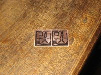
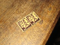
So I did the PCBs this evening. I use a laser-printed mirror image which I ironed on, and then used a pen to try it reinforce it where it looked a little thin. The final result is better than I expected, since this is my first try at doing my own boards. I've posted photos below of the boards with the design printed on, but before etching, and one of them after. In real life they are much shinier than they appear in the second photo. Oh, and the layout is a little different from the one I posted above, since I had to redo it at a higher pixel count, but the basic design is similar, and they are indeed 25mm x 25mm as I estimated above.
SMD parts arrived from Farnell-Newark in SP today, so I can get soldering...
One question: Judging by discussions of similar amps on other threads, I'm guessing this will need a 160VA trafo at bare minimum, more like 300VA to be on the safe side. I *have* a 19VDC (approx) power supply I made for another project which I was thinking of rebuilding for this one, to save a little cash on the trafo, but its a little small. Here in Brazil they don't sell by power rating, but by current rating; in this case, a 18-0-18 secondary at 5A, which (unless I have misunderstood something) makes it a 180VA. Can I hear opinions on whether this is likely to be sufficient? If I really need something like a 18-0-18 at 10A then this would be very expensive... possibly changing the basic design to do two monoblocks would be cheaper... Again, anyone have an opinion?
Cheers
Nigel
Attachments
Hi Juma,
Thanks for the reply - Good news if 5A is going to be OK. Actually I was planning on doing a capacitance multiplier circuit (from the ESP site) that I used before and liked, but which will probably drop more voltage than that.
I can't remember now how much output voltage I'm getting, but it's probably 19-20VDC. I'll measure it later and post.
Cheers
Nigel
If you don't use some kind of Vref in the base circuit it won't drop more than 2-3 V at most. Cap. multiplier is a valid solution too, but it will be another source of heat (Pd=Vdrop * I)
The PSU in question was built for a Hiraga 20W amp a couple of years ago but I always wondered if it was a little underpowered. I can use it as it is, alter it, upgrade it, or just pull it apart and use the pieces to make a new one.
I just pulled it out to measure its output - It's giving a little more than 21VDC without load, sagging to to a little more than 19VDC with a 18R load. (Meaning about 1A current being drawn, if I haven't made another mistake with Ohm's Law...
). In it's final use it will probably sag a little more than that, since we'll be drawing more current, but we seem to be in the right ballpark.I previously measured the ripple voltage on this (with some help from a tech in Elec.Eng and his o-scope) as about 50mV peak-to-peak, which seems pretty good (although not fantastic) for an unregulated supply. Since the PSU is in a separate case (and the active parts are heatsinked) the extra heat generated isn't a real problem. I am also considering putting some more filtering in the amp chassis near the connection to the boards, which could be something simple like a pair of filtering caps, or could be another capacitance multiplier, if I felt the need to drop the voltage a little further - although it doesn't look to me like it will be necessary.
As always, any comments and advice much appreciated.
Cheers
Nigel
50mV peak-to-peak is OK. As you wrote, you'll have a bit more sag if you plan to use that PS for both channels (2.4A - 2.6A constant draw), but anyway, that's it - you got it where you wanted it
If you plan to add more caps, try to put a 10,000 - 15,000 uF on the capacitance multiplier's output, your amp will love it.
If you plan to add more caps, try to put a 10,000 - 15,000 uF on the capacitance multiplier's output, your amp will love it.
50mV peak-to-peak is OK. As you wrote, you'll have a bit more sag if you plan to use that PS for both channels (2.4A - 2.6A constant draw), but anyway, that's it - you got it where you wanted it
If you plan to add more caps, try to put a 10,000 - 15,000 uF on the capacitance multiplier's output, your amp will love it.
I was thinking of putting a pair like like that *in* the amp chassis - I read somewhere this helps with noise/hum or something from having a 1m/2m cable connecting the PSU with the amp itself. Is it worth putting a snubber cap on these? Maybe a 100nF or 1uF film cap?
Anyhow, thanks for all the help.
Cheers
Nigel
Cable won't do any harm if it's properly mechanically and electrically done (thick wires, quality connectors, decoupling caps).
Snubber is cheap and easy to try, find out what you like the best and how far you want to go - some guys reported lately good results with motor-run caps (ca. 50uF) as the last components in PS chain - options are many and most of them won't hurt your budget much
- Status
- This old topic is closed. If you want to reopen this topic, contact a moderator using the "Report Post" button.
- Home
- Amplifiers
- Pass Labs
- Is a mini-Aleph using BF862 possible?