Thanks so much!! (I'm Enlightened)
So basically it's a trade-off of feedback amount and figures at low and high output level. I didn't notice it because I was looking only THD at 1W.
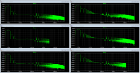
Below, I played with resistors values with total R10/R11 + R12/R13 = 0.75 Ohm
Top is R10/R11 = 0 Ohm, R12/R13 = 0.75 Ohm
Middle is R10/R11 = 0.25 Ohm, R12/R13 = 0.5 Ohm
Bottom is R10/R11 = 0.325 Ohm, R12/R13 = 0.325 Ohm
Left is 1W operation, right is 25W operation
@1W :
It is clear that top trace measures much better THD, with the least 2nd Order Harmonic.
Middle trace has more 2nd, similar 3rd but less 4th harmonic (the one which is more harmful)
Bottom trace has similar signature to middle trace, but at a slightly higher level
@25W :
The best trace is (rather clearly) middle trace which has the least 3rd and higher order harmonics (and about equal 2nd)
Again, lower trace is similar to middle trace but a bit worse.
Top trace has clearly more higher order harmonics which you won't want since they are more harmful
So once more, it seems there is a sweet spot of feedback amount, and in my case, it's with about 1/3 resistance on "top" and 2/3 resistance below.
(Connoisseurs will recognize this post owes a lot to several of Nelson Pass's great papers)
So basically it's a trade-off of feedback amount and figures at low and high output level. I didn't notice it because I was looking only THD at 1W.
Below, I played with resistors values with total R10/R11 + R12/R13 = 0.75 Ohm
Top is R10/R11 = 0 Ohm, R12/R13 = 0.75 Ohm
Middle is R10/R11 = 0.25 Ohm, R12/R13 = 0.5 Ohm
Bottom is R10/R11 = 0.325 Ohm, R12/R13 = 0.325 Ohm
Left is 1W operation, right is 25W operation
@1W :
It is clear that top trace measures much better THD, with the least 2nd Order Harmonic.
Middle trace has more 2nd, similar 3rd but less 4th harmonic (the one which is more harmful)
Bottom trace has similar signature to middle trace, but at a slightly higher level
@25W :
The best trace is (rather clearly) middle trace which has the least 3rd and higher order harmonics (and about equal 2nd)
Again, lower trace is similar to middle trace but a bit worse.
Top trace has clearly more higher order harmonics which you won't want since they are more harmful
So once more, it seems there is a sweet spot of feedback amount, and in my case, it's with about 1/3 resistance on "top" and 2/3 resistance below.
(Connoisseurs will recognize this post owes a lot to several of Nelson Pass's great papers)
Attachments
Well done, Fred!
I took the simpler way out and figured Nelson listened to a bunch of different permutations before picking one -- and so duplicated his 2/5 top and 3/5 bottom.
Cheers,
Jeff.
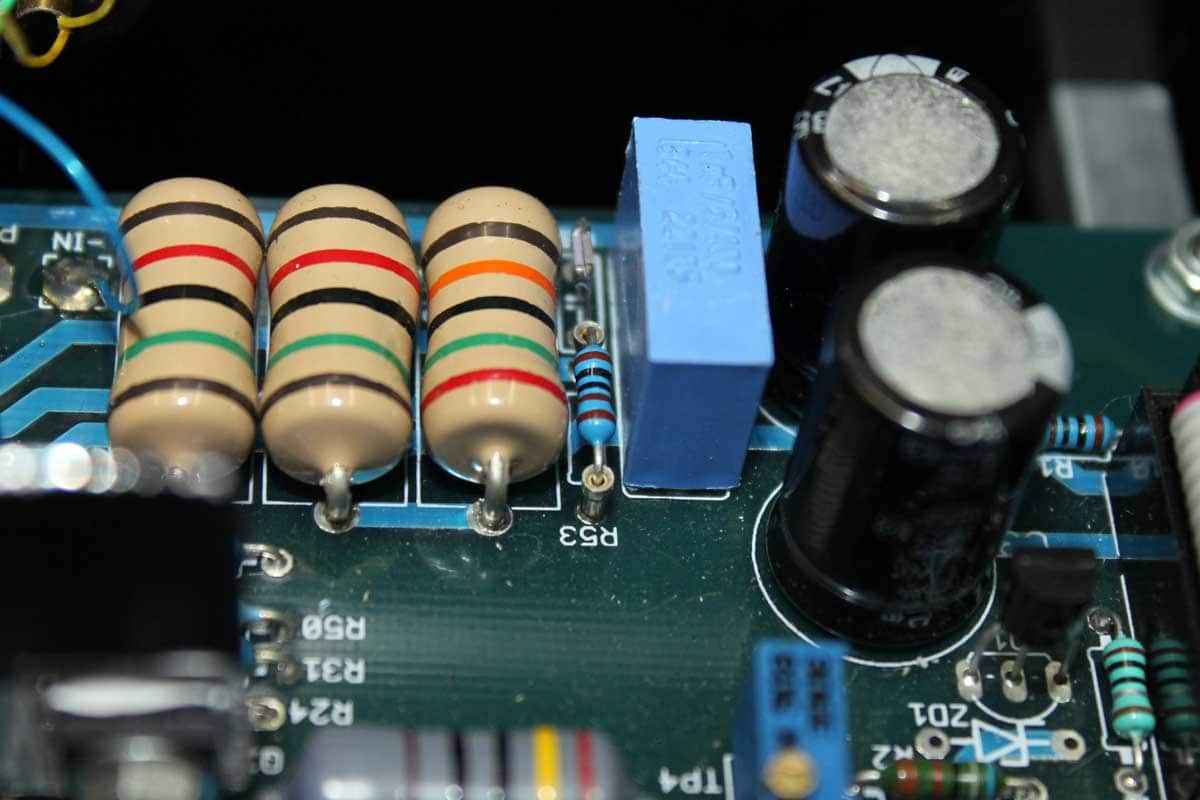
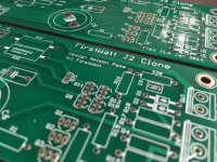
PS: ZM had a stupendous idea in his Babelfish JX thread where he used socket pins to mount resistors one might want to experiment with (R53 in the picture). Not sure you can get them for fat-leaded 3watters, though.
I took the simpler way out and figured Nelson listened to a bunch of different permutations before picking one -- and so duplicated his 2/5 top and 3/5 bottom.
Cheers,
Jeff.
PS: ZM had a stupendous idea in his Babelfish JX thread where he used socket pins to mount resistors one might want to experiment with (R53 in the picture). Not sure you can get them for fat-leaded 3watters, though.
it's already well proven that fastest and easiest way for ruining perfect Papamp is - to Babelfish it

I'd need original perfect schematic so I can ruin it lol!
Seriously, since I don't know the values of original amp, I needed to use brute force and experiment...
FWIW, here's a pin socket that will fit Papa's favourite Panasonic blue jobbies: 0300-1-15-01-47-01-10-0 Mill-Max | Mouser Ireland
I get much better improvement in simulation (-20dB 2nd Harmonic @1W) by using a Semisouth in the CCS than paralleling them in bottom part
At high power the improvement is a bit less but still significant :10-15dB
I'd say it's a better use of the part.
Also, I find it harder to tune everything with parallel output JFETs
At high power the improvement is a bit less but still significant :10-15dB
I'd say it's a better use of the part.
Also, I find it harder to tune everything with parallel output JFETs
Hi Fred,
I'm mostly paralleling the SemiSouths and IRFPs to get to 50w. I don't think you can do that without paralleling (or setting the thing on fire).
What is the delta between your H2 and H3? I get the impression that keeping that greater than 15dB is more important than the absolute level of H2.
Assuming you started with my .asc (and have the .four statement in it), go to the View menu and open the Spice Error Log. About 1/2 way down it will show the first 9 harmonics and then the THD.
One last question: when you say you find it "harder to tune everything with parallel outputs" do you just mean setting up the bias, optocoupler and offset, or is there some other tuning I'm missing?
Cheers,
Jeff.
I think I now understand how this thing works
Been running hundreds of Spice simulations and I think I got to the lowest THD figures achievable with these parts (even lower than FirstWatt Original J2... but hey that's just a Spice simulation lol)
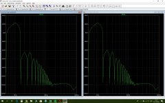
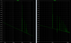
Below are 2 simulations @25W with various resistor values below CCS.
Which on would be considered better ?
Left : Measures slightly better THD 0.061%, has less H2 and about equal H3 and higher Harmonics
Right: Measures slightly worse (0.08%) but has less feedback
In other words: Should I trust figures, or is it preferrable to have a bit of H2 harmonics considering that it's achieved with a bit less feedback ?
Been running hundreds of Spice simulations and I think I got to the lowest THD figures achievable with these parts (even lower than FirstWatt Original J2... but hey that's just a Spice simulation lol
)Below are 2 simulations @25W with various resistor values below CCS.
Which on would be considered better ?
Left : Measures slightly better THD 0.061%, has less H2 and about equal H3 and higher Harmonics
Right: Measures slightly worse (0.08%) but has less feedback
In other words: Should I trust figures, or is it preferrable to have a bit of H2 harmonics considering that it's achieved with a bit less feedback ?
Attachments
Fred,
When running FFTs you need to change the max time-step from 10u to 1u, and the total time from 0.002sec to something like 0.2sec. I'm not sure it will change the numbers, but it will at least make the data look more trustworthy.
I think the factory J2 has something like 15dB between H2 and H3. That's what I'd be shooting for, but some people like more or less H3.
H4 and above, though, I think are uniformly disliked. I'd try to minimise them rather than the THD.
Cheers,
Jeff.
Fred,
When running FFTs you need to change the max time-step from 10u to 1u, and the total time from 0.002sec to something like 0.2sec. I'm not sure it will change the numbers, but it will at least make the data look more trustworthy.
Thanks! I didn't know.
It sure looks a lot better ! more like a pure Dirac , but the values are essentially unchanged
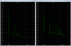
The one on the left certainly has the higher order harmonics in better control.
When I say Left/Right, I mean left and right picture.
In both picture: Left diagram is @1W, Right one @15W
There is not too much difference between the two in 3rd and higher order harmonics @15W. The only significant difference is 2nd Order harmonic.
I was basically wondering whether having H2 > H3 (as in right picture) was actually desirable for the sound, or if one would want to seek the lowest possible THD (as in left picture)
Ahh... I misread them. So the higher order harmonics really are pretty much the same, and it's just the ratio of 2 to 3 and the overall level.
I haven't experimented with this myself, but I think conventional wisdom is to prefer H2 > H3 over absolute THD (ie: the right one).
I haven't experimented with this myself, but I think conventional wisdom is to prefer H2 > H3 over absolute THD (ie: the right one).
- Home
- Amplifiers
- Pass Labs
- FirstWatt J2