oh yes ...... when you use few proper jfets as CCS for JFet LTP , at least you're getting something in TempCo department
if you're using BJT , you're loosing something in TempCo department
so , at least make that BJT SSC proper one ; if you use governing bjt small and actual series bjt slightly larger , there is no need for series resistor between CCS and LTP , to take some burden from sissy parts in CCS
you always need to take dissipation in account
and use 8R as load , when simulating ; 47K is high , even for dampening purpose
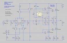
While playing around with ZenMod's feedback current source, it occurred to me that I don't need all the "extra" parts. As he himself alluded to, if I beef up (and heatsink) the primary PNP then I can drop the resistor between the CCS and the LTP. And without the zener to contend with, the bypass cap is probably not necessary.
Which leads me to:
Which leads me to:
Attachments
It definitely runs, and produces some impressive THD numbers. (It'll take me a while to get my head around it though; I'm a novice on the analog side of things.)
Here's the lib if you want to try it out.
Oh!
 You are luckier than me.
Apparently the .txt sufix forbids the program to use it??
Edit: I forgot to thank you for the file.
I lack also the .model for K170/J74
Try to see if it works with half the CFP units.
Also, take a look at W. Jung´s article about CCS. Lots of versions to try.
Good luck.
M.
Last edited:
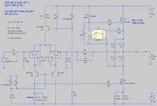
The purpose of the 36V rails is to drive an F4 to 100W+ into 4 ohms.
But it seemed a shame to waste them when the J2-esque was on its own. So:
Interestingly, even though I reduced the bias slightly, the distortion figures still dropped in half @ 1W.
Cheers,
Jeff.
But it seemed a shame to waste them when the J2-esque was on its own. So:
Interestingly, even though I reduced the bias slightly, the distortion figures still dropped in half @ 1W.
Cheers,
Jeff.
Attachments
I lack also the .model for K170/J74
Here is what I had (copied from the forum somewhere)
Don't know how good they are...
*2SK170
* 20mA 400mW LowNoise Dep-Mode pkg:TO-92B 3,1,2
.MODEL 2SK170 NJF(Beta=59.86m Rs=4.151 Rd=4.151 Lambda=1.923m
+Vto=-.5024 Cgd=20p Pb=.4746 Fc=.5
+Cgs=25.48p Is=8.477p
+Kf=111.3E-18 Af=1)
*2SJ74
*Toshiba Dep-Mode 20mA 400mW LowNoise pkg:TO-92B 2,1,3
.MODEL 2SJ74 PJF(Beta=92.12m Rs=7.748 Rd=7.748 Lambda=4.464m
+Vto=-.5428 Cgd=85.67p Pb=.3905 Fc=.5
+Cgs=78.27p Is=12.98p
+Kf=26.64E-18 Af=1)
Fred
So I've been experimenting with the J2-esque Spice model from Jeff (Thanks a lot by the way for doing all the hard work!)
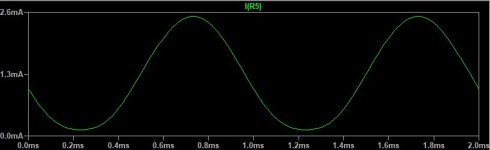
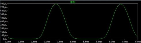
Some might say that I'm stating the obvious, but I noticed that depending on the CCS resistor values (R10/11 and R12/13) , there are 2 ways you operate the optocoupler:
- either in the "linear" region
- or at the diode's conduction threshold, where it might stop conducting on the lower part of the sine.
Interestingly , it works very well in both cases, but using the optocouple in the "linear" part of the diode's forward current (obviously?) gives a slightly better THD, so that's where you want to use it I guess
Attachments
The next thing I noticed (and really I might be totally wrong, not being a pro with Spice, and admitedly not fully understanding the circuit operation....) is that THD seems to be significantly better if you keep R10/R11 at 0 and put all of the resistance in R12/R13.
Also, clipping is symetrical in this case, which seems to give a higher power before signal starts to get really dirty
Which leads me to a beginner's question..: why did everyone put the output somewhere in the middle of a voltage divider ?? (except the fact that Nelson did it according to J2 pictures lol)
I get much better figures by just ignoring R10/R11
Last edited:
Interesting results, Fred. I hadn't been paying enough attention to the optocoupler and was indeed running it out of bias near clipping.
The unbalanced source/drain degeneration is also interesting. I'm not sure about running the CS's degeneration all the way to 0, but further unbalancing seems warranted (and also runs the unobtainium SemiSouth a bit cooler).
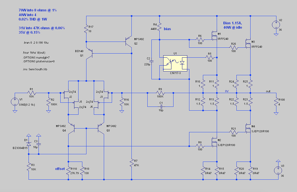
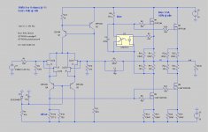
So here's an interesting beast. I adjusted things so that it's voltage limited at 50W into 8 ohms and current limited at 50W into 4 ohms. It also makes use of both of Fred's discoveries:

I also attached some .asc's. J2_dbl.asc is the above, while J2_FCCS.asc is the undoubled output version with higher rails (and as yet without Fred's optimisations).
The unbalanced source/drain degeneration is also interesting. I'm not sure about running the CS's degeneration all the way to 0, but further unbalancing seems warranted (and also runs the unobtainium SemiSouth a bit cooler).
So here's an interesting beast. I adjusted things so that it's voltage limited at 50W into 8 ohms and current limited at 50W into 4 ohms. It also makes use of both of Fred's discoveries:
I also attached some .asc's. J2_dbl.asc is the above, while J2_FCCS.asc is the undoubled output version with higher rails (and as yet without Fred's optimisations).
Attachments
The next thing I noticed (and really I might be totally wrong, not being a pro with Spice, and admitedly not fully understanding the circuit operation....) is that THD seems to be significantly better if you keep R10/R11 at 0 and put all of the resistance in R12/R13.
Also, clipping is symetrical in this case, which seems to give a higher power before signal starts to get really dirty
Which leads me to a beginner's question..: why did everyone put the output somewhere in the middle of a voltage divider ?? (except the fact that Nelson did it according to J2 pictures lol)
I get much better figures by just ignoring R10/R11
Setting R10/R11 to lower values increases the open loop gain of the
circuit, so you will enjoy more feedback and thus lower distortion -
at lower levels.
The problem then is that the current source is doing more of the work
which is fine when the waveform is positive, not so much when it is
negative, where the current source goes into cutoff at a figure
approaching 1/2 output current as compared to more symmetric operation.
The result resembles a large crossover notch. For a given load, you
can increase the bias current until that goes away, but now you are
approaching twice the dissipation for a given output rating.
- Home
- Amplifiers
- Pass Labs
- FirstWatt J2