J2 review on 6moons
YouTube - Hchicha Mahna yal mahna
Edit: Pardon, that was of course the wrong link! Sooo sorry for it!
Oh look, all smilies are blue! Nice color! I like it!
YouTube - Hchicha Mahna yal mahna
Edit:
Pardon, that was of course the wrong link! Sooo sorry for it! Oh look, all smilies are blue! Nice color! I like it!
F1 With SIC FETs
So an F1 with SIC FETs would seem to be an attractive proposition!
RC
Originally Posted by Jon Ver Halen
I think it is more than just the damping factor, but I have not done a close side by side comparison. The J2 sounds just a touch sweeter, and a little "softer" in comparison to the F1. F1, as I recall, is a tad more dynamic. They sound extremely similar, with just minor shades of coloring. Not sure which one is closer to the mythical "straight wire with gain", and you get to decide which one sounds better to you.
So an F1 with SIC FETs would seem to be an attractive proposition!
RC
So an F1 with SIC FETs would seem to be an attractive proposition!
RC
Probably! So feel free to ask SemiSouth to develop a P-channel-JFet! Doh!
Doh! I think my brain was on a coffee break as I am familiar with the F1 circuit!
RC
Probably! So feel free to ask SemiSouth to develop a P-channel-JFet!
Doh! I think my brain was on a coffee break as I am familiar with the F1 circuit!
RC
Hi gents,
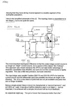
please find attached a try about finding out the schematic of the J2 based on the 6moons pics and the provided information with respect to this thread.
Regards, Jürgen
Hi Jurgen! I don't think we need the current limiter (for our purpose -don't try to connect speaker cables while the amp is on) and the Gate resistors on the SS Jfets.

Hi gents,
please find attached a try about finding out the schematic of the J2 based on the 6moons pics and the provided information with respect to this thread.
Regards, Jürgen
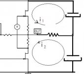
Making the resistors equal should produce a constant voltage across that pair. (An increase of current in one half is compensated by the same decrease on the other half.)
So making a constant current source
Then the sensing could be picked up from the lower resistor only.
Doh! I think my brain was on a coffee break as I am familiar with the F1 circuit!
RC
Oh, chin up. I'm just a swot!
I guess you know a lot more about circuitry than I do! What about the TL431 shunt reg that N.P. used on F4 for the bias refrence? I suppose just a string of diodes would work there too. But I don't think that is very elagant as N.P. always is. I think it would be good to reject +V supply noise if there where at least a simple jfet I source or somthing biasing the bias refrence that would be good?
For the input:
What is that 1.2V at the diff load/output gate. Did he not mention somewhere that he's biasing that Semi-South part at 1.5V. I should look at the datasheet ha? With a source resistor of .47(typical) or maybe less from the internal picture(2X Rs), there would need to be another .5 -1 volt or so at the diff load R. So we need about 2-2.5V at the diff load R. I guess that would make the diff load R about 220 ohm. I'm sure he has lots of those binned somewhere... But wait, why is he using dual JFETs on the diff? More current? Same ol 5mA but better Pd? More gain? Hmmm...
Also I would suppose he would drop some of that +V on an R rather than dissapate all the extra power in the 2 2sk170s of the current source. That would be a little high even for 2 of 'em. I think the BA front end does that too?
And, you have a pot in your pic? Dosen't the reveiw comment that there is no adjustments? He hasent used one there before that I can remember and I think he likes the no adjustment Poke-Yoke approach.
I think we're getting somewhere but we need to gather a few more brains...
Last edited:
J2 in the Air
Was just eMailed by Mark at Reno HiFi... Phil your F.W. J2 is in the mail...eta Monday the 26th....
Oh Boy!!!
Many Thanks to the Pass Clan!!!!!
I told friend Robert Hall I was infected by the N1P1 virus. Must have drank too deeply from the damn kool-aid Jon was passing out at RMAF.
Phil
Santa Fe
First listen will be with Feastrex 5Dnf in a Makio Box...Then on to OB Lowther Field coils etc. etc. Let the fun begin... I think my trusty 45 amp is getting nervous.
Pass "Nameless" amp
The new Pass single with depletion mode output thread is now split out to here:
http://www.diyaudio.com/forums/pass-labs/153832-pass-nameless-amp-baf.html
When he comes up with a different name we'll change the title!
Mark
The new Pass single with depletion mode output thread is now split out to here:
http://www.diyaudio.com/forums/pass-labs/153832-pass-nameless-amp-baf.html
When he comes up with a different name we'll change the title!
Mark
What about the TL431 shunt reg that N.P. used on F4 for the bias refrence? I suppose just a string of diodes would work there too. But I don't think that is very elagant as N.P. always is. I think it would be good to reject +V supply noise if there where at least a simple jfet I source or somthing biasing the bias refrence that would be good?
For the input:
What is that 1.2V at the diff load/output gate. Did he not mention somewhere that he's biasing that Semi-South part at 1.5V. I should look at the datasheet ha? With a source resistor of .47(typical) or maybe less from the internal picture(2X Rs), there would need to be another .5 -1 volt or so at the diff load R. So we need about 2-2.5V at the diff load R. I guess that would make the diff load R about 220 ohm. I'm sure he has lots of those binned somewhere... But wait, why is he using dual JFETs on the diff? More current? Same ol 5mA but better Pd? More gain? Hmmm...
Also I would suppose he would drop some of that +V on an R rather than dissapate all the extra power in the 2 2sk170s of the current source. That would be a little high even for 2 of 'em. I think the BA front end does that too?
And, you have a pot in your pic? Dosen't the reveiw comment that there is no adjustments? He hasent used one there before that I can remember and I think he likes the no adjustment Poke-Yoke approach.
I think we're getting somewhere but we need to gather a few more brains...
Hi flg,
yes, you are right, Mr Pass`s designs allways have that intelligent simplicity. Of course you could find a design that is meeting the functional requirments but aren`t there always much more components than in his circuit?
Sorry for the bad drawing, its not 1.2V but 1.7V on the Resistor. This data is a rough guess only - not talking about any optimisation like the "sweet spot".
TL431 - I do not recognize any when I look at the published pics. What I see is a ZTX like component and my guess was protection. Thinking complicated I could assume some Taylor-Follower configuration or somethin` else...
Ah yes, the pot - I am sure you`ll also see that component looking at the pics at 6moons. Adjust what? Offset, Idle current, combined or something else.
My assumption is not the latest one, more a starting point until we might have the magical components to fit in.
Regards, Jürgen
Hi there,
forgot to mention something about the opto-coupler. I am not quite sure but could it be that it`s working like a current controlled current source (CTR!) and so we gain the functionality of rail decoupling very easily? Again, Mr. Pass is using simple circuits with lots of thought....
Jürgen
forgot to mention something about the opto-coupler. I am not quite sure but could it be that it`s working like a current controlled current source (CTR!) and so we gain the functionality of rail decoupling very easily? Again, Mr. Pass is using simple circuits with lots of thought....
Jürgen
I told friend Robert Hall I was infected by the N1P1 virus. Must have drank too deeply from the damn kool-aid Jon was passing out at RMAF.
Phil
Santa Fe
Phil:
I am beginning to understand your problem. That was a bottle of single malt whiskey in the bathroom, not kool-aid.
- Home
- Amplifiers
- Pass Labs
- FirstWatt J2