I am mounting the two transformers vertically, mounted on an aluminium plate. It occurred to me that I could save some more space by mounting a second set of much smaller transformers (for the front end supply) the other side of the metal plate using the same mounting bolts. Will the big power transformers cause inductance in the smaller transformers either through the metal plate or via the shared mounting bolts?
Thanks Andrew once again. As a matter of general physics does the intervening metal plate reduce the influence of hysteresis between the two transformers? I'm thinking it certainly won't abolish it when you think of a magnet below a metal tray with iron filings on the other side and how does a GOSS band work?
Sorry this is turning into a Wikipedia enquiry.
Sorry this is turning into a Wikipedia enquiry.
Cable shielding:
I'm running my mains cable close to one of the power boards. I am already using Supra shielded cable to reduce radiation from the mains voltage but I have also put a braided sleeve around it to increase protection from radiation. However, where to ground the braid? I have been doing some reading on the subject and low frequency radiation it is suggested requires grounding at one end but there are those that suggest to protect from higher radiation frequency or magnetic interference both ends should be grounded.
What is the verdict?
Burning Amp Lamp
Burning Amp Lamp
Hello to all my fellow Burning Ampers (or should that be Burning Amperes?).
I have had many hours of enjoyment listening to my BA-2 amplifier over the past year. My thanks again go out to the man who made this possible.
One thing I neglected in my haste to get the amp working was a power on indicator. This oversight has added to my electric bill, since, more often than not, I forget to turn the amp off when I am finished listening.
Recently I decided to move the amp back to my workbench and install something to let me know when the amp is powered on.
My first inclination was to stick a simple LED on or behind the front panel, which I made from a 19 inch dual height rack mount perforated metal security cover. I thought using the security cover for the front panel would give me some degree of shielding from electrical interference while still letting me see the internal circuitry of the amplifier. I have a bad habit of opening equipment up from time to time to look inside if I can't see inside without taking covers off!
I went digging through my parts boxes and ran across a tri-color (RGB) Cree LED illuminator PCB that I had bought for another project and never used, and my mind started thinking of somehow using it as a combination amp interior illuminator and power on indicator. I thought it would be cool to be able to dial up any color I want to light up the inside of my amp.
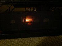
As I thought a while about various ways I might make best use of the device, I thought back to my younger days when I used to stare inside the back my dad's tube radio while he listened to the baseball games he dearly loved. The warm orange glow from the tube heater filaments was bright and cheery looking, and I fell in love with that look. It struck me that I would love to recapture that same look inside my Burning Amp, which has the physical warmth of a tube circuit due to the high bias of its impeccable Nelson Pass design, but not "that tube glow" that I love.
So I sketched out a simple triple adjustable constant source to drive the LED board. I built and wired the circuit across the second set of power supply filter caps so that the LED's light up as the amp is powered up.
There is enough delay in the RC supply circuit and inrush thermistor that the LED's come up gradually, looking very much like the filament light in a tube amp upon turn on. I mounted a white translucent plastic rod over the LED emitter so that the illumination would be diffused and spread throughout the interior of the amp with a good portion of it being visible through the perforated front panel.
With the circuit completed and in place, I turned the room lights down and started playing with the three color mix pots in search of that perfect filament glow.
I found that I didn't need the blue LED at all, and it was reasonably easy to mix the red and green LED's to achieve the look I wanted.
I hooked the amp back up to my living room system and turned the room lights off. When I hit the power switch and watched the amp power on, I couldn't help smiling at its fine new look.
And there was a bonus that I hadn't anticipated--when the amp is powered down, the discharging power supply caps allow the illuminator to gradually dim, adding very much to the tube illumination illusion.
So now my Burning Amp is finally finished, and my support of the local electrical company should be a little less.
If anyone is interested in the circuit, let me know and I will gladly share it with the group.
Thanks to everybody here. I really love learning from you all.
Burning Amp Lamp
Hello to all my fellow Burning Ampers (or should that be Burning Amperes?).
I have had many hours of enjoyment listening to my BA-2 amplifier over the past year. My thanks again go out to the man who made this possible.
One thing I neglected in my haste to get the amp working was a power on indicator. This oversight has added to my electric bill, since, more often than not, I forget to turn the amp off when I am finished listening.
Recently I decided to move the amp back to my workbench and install something to let me know when the amp is powered on.
My first inclination was to stick a simple LED on or behind the front panel, which I made from a 19 inch dual height rack mount perforated metal security cover. I thought using the security cover for the front panel would give me some degree of shielding from electrical interference while still letting me see the internal circuitry of the amplifier. I have a bad habit of opening equipment up from time to time to look inside if I can't see inside without taking covers off!
I went digging through my parts boxes and ran across a tri-color (RGB) Cree LED illuminator PCB that I had bought for another project and never used, and my mind started thinking of somehow using it as a combination amp interior illuminator and power on indicator. I thought it would be cool to be able to dial up any color I want to light up the inside of my amp.
As I thought a while about various ways I might make best use of the device, I thought back to my younger days when I used to stare inside the back my dad's tube radio while he listened to the baseball games he dearly loved. The warm orange glow from the tube heater filaments was bright and cheery looking, and I fell in love with that look. It struck me that I would love to recapture that same look inside my Burning Amp, which has the physical warmth of a tube circuit due to the high bias of its impeccable Nelson Pass design, but not "that tube glow" that I love.
So I sketched out a simple triple adjustable constant source to drive the LED board. I built and wired the circuit across the second set of power supply filter caps so that the LED's light up as the amp is powered up.
There is enough delay in the RC supply circuit and inrush thermistor that the LED's come up gradually, looking very much like the filament light in a tube amp upon turn on. I mounted a white translucent plastic rod over the LED emitter so that the illumination would be diffused and spread throughout the interior of the amp with a good portion of it being visible through the perforated front panel.
With the circuit completed and in place, I turned the room lights down and started playing with the three color mix pots in search of that perfect filament glow.
I found that I didn't need the blue LED at all, and it was reasonably easy to mix the red and green LED's to achieve the look I wanted.
I hooked the amp back up to my living room system and turned the room lights off. When I hit the power switch and watched the amp power on, I couldn't help smiling at its fine new look.
And there was a bonus that I hadn't anticipated--when the amp is powered down, the discharging power supply caps allow the illuminator to gradually dim, adding very much to the tube illumination illusion.
So now my Burning Amp is finally finished, and my support of the local electrical company should be a little less.
If anyone is interested in the circuit, let me know and I will gladly share it with the group.
Thanks to everybody here. I really love learning from you all.
Attachments

post edited schematic with values what you set and where
D is node with cap in line , so there is always 0 Volts , so I'm puzzled how you "set" that;
set circuit exactly as Papa drew on sch , without measuring voltage at D node
if you put , say , 10 K resistor ( bleeder function , to prevent D from floating) from D to gnd , you'll see that's the case
however , D is proper out node of stage , while node marked out is connection for bootstrap potential , so using D node as out is normal
again , connect node marked Out to amp's out for best performance , or leave it unconnected for lesser performance , counting on fact that you anyway need lesser gain , so there is no such need for bootstrapping
anyway - you'll have too much gain for any power stage having own gain ( F5 and F6, too )
so , as Papa wrote in article , you can alter gain for your needs :
The gain of this front end is set at about X 6, or 15 dB. You can have higher gain simply by changing R203 and R204 to higher values. You can double the gain (to about 20 dB) by increasing these to 100 Kohm, and you can push it to 150 Kohm (about 23 dB) without changing the compensation capacitors.
Last edited:
Thanks Oh mighty ZM.
I adjusted the P201 until I got 0v offset at D.
Now, I connected to the F5 (without the output) and it works and I do get more gain. So now, I figure that I'm ok to connect the output to the output of the amp. (I'll probably try on the F6 since the F5 is all cased up)
I got that about the x 6 gain but conversely, If I need less gain, I can lower the values of r203,r204 to say, 22k.
Have I finally understood this circuit?
Other thing, can I power this FE with a salas shunt?
thanks again for your help.
Thanks Oh mighty ZM.
I adjusted the P201 until I got 0v offset at D.
re-read what I wrote in previous post
see at picture :
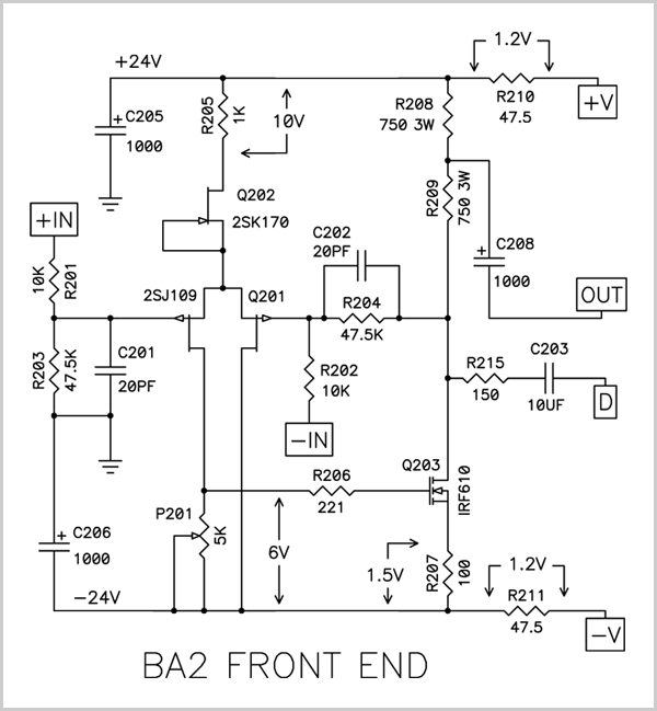
you need to adjust P201 to get 0V at drain of Q203
......... node with R215 , to be more illustrative
what Pa wrote in article , mentioning output ....... is most probably addressed on biasing of output stage , not FE
Now, I connected to the F5 (without the output) and it works and I do get more gain. So now, I figure that I'm ok to connect the output to the output of the amp. (I'll probably try on the F6 since the F5 is all cased up)
connect and listen ; choose what you like more - bootstrapped to output stage or not
I got that about the x 6 gain but conversely, If I need less gain, I can lower the values of r203,r204 to say, 22k.
.
yes
Other thing, can I power this FE with a salas shunt?
why not ?
Iq is in range of 25mA/rail/channel ; leave out (bridge) R210 and R211 , you can leave C205 and C206 in
programmed current for any shunt reg need to be at least 50mA/channel , each rail
max 75mA , no need for more
Last edited:
doneyou need to adjust P201 to get 0V at drain of Q203
......... node with R215 , to be more illustrative
what Pa wrote in article , mentioning output ....... is most probably addressed on biasing of output stage , not FE
will remove and use them to parallel r203/r204 to lower gainIq is in range of 25mA/rail/channel ; leave out (bridge) R210 and R211 , you can leave C205 and C206 in
done
will remove and use them to parallel r203/r204 to lower gain
you're pulling my leg , yes ?
there is a slight difference in value ........ around 1000-fold ..........

you're pulling my leg , yes ?
there is a slight difference in value ........ around 1000-fold ..........
my bad, I gotta get new glasses or get more sleep.
thanks again, next step is to try out with F6
I've been planning to use the BA-3 front end (now pushing SE outputs) for an upcoming complementary and/or balanced build. I bought the BA-GS V2.0 FE to use with the SE boards I have, but it appears the 2SJ109 is non stock and only only available on eBay.
I'm aware of this from the article: "Q201 is a dual matched pair of P channel Jfets, part 2SJ109. These are in scarce supply (although the recipients of Burning Amps will each get a pair). They can be substituted with matched 2SJ74 types, and a number of other parts will function with lesser performance."
Need a recommendation on the best approach, and if I use the matched pair is that just a simple side by side mounting. The pin pattern suggest that, but I've seen pairs strapped face to face in some cases.
Also not clear - is the bias board at the store considered universal now? I can see some version number differences but the photos look the same.
Last edited:
Need a recommendation on the best approach, and if I use the matched pair is that just a simple side by side mounting. The pin pattern suggest that, but I've seen pairs strapped face to face in some cases.
A pair of matched J74 will do the job. I need to look at the pcb mounting to see exactly what the arrangement will be.
Any J109 from ebay is fake.
Most certainly no. The bias for the SE board is completely different than the Push-Pull.Also not clear - is the bias board at the store considered universal now? I can see some version number differences but the photos look the same.
- Home
- Amplifiers
- Pass Labs
- Burning Amplifier BA-2