BA-2 problems
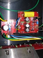
Backbones: Yes, the OUT from the output boards goes to the + speaker out terminal. The (-) speaker out terminal goes to the signal ground. Thanks!
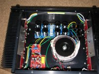
buzzforb: The plate is just holding the output board against the sink. There are 6 standoffs on the board, the plate holds the board stable, and I verified that no metal from the holddown plate is touching any exposed traces on the board. Each MOSFET is secured to a tapped hole on the sink with compound and pads between the mosfet and sink. Thanks.
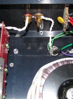
ZM: I have rca and xlr inputs. switch is used to ground pin 3 of the xlr to pin 1 when the rca input is used. All connections have been verified as correct. Thanks.
Matt
Backbones: Yes, the OUT from the output boards goes to the + speaker out terminal. The (-) speaker out terminal goes to the signal ground. Thanks!
buzzforb: The plate is just holding the output board against the sink. There are 6 standoffs on the board, the plate holds the board stable, and I verified that no metal from the holddown plate is touching any exposed traces on the board. Each MOSFET is secured to a tapped hole on the sink with compound and pads between the mosfet and sink. Thanks.
ZM: I have rca and xlr inputs. switch is used to ground pin 3 of the xlr to pin 1 when the rca input is used. All connections have been verified as correct. Thanks.
Matt
Hi Matt,
I know this might sound wrong headed but have you actually wired up some speakers (not the good ones) and listened?
After all if the bias has been set and you can adjust the dc offset then the power boards are working fine. Could be the front end by a process of elimination.
Chris
I know this might sound wrong headed but have you actually wired up some speakers (not the good ones) and listened?
After all if the bias has been set and you can adjust the dc offset then the power boards are working fine. Could be the front end by a process of elimination.
Chris
trouble with BA-2 mono
Backbones: Hi Chris, yes, I did hook one up, did get sound, very quiet, then stopped as I increased the volume, as the 1.5amp fuse I had onboard blew. Same result with both monoblocks and even one monoblock with another gain stage board that I assembled with totally new components, all checked for proper values.
I have looked at these front end boards many times, and checked the components for orientation, value, etc, but plan to do that all over again this weekend.
Matt
Hi Matt,
How are things progressing? Two things that came to mind whilst doing nothing in particular over the weekend were: fake components on the semiconductor side and the other as to whether you have disconnected the front end and fed a signal into the power boards directly to see how they behaved.
Best wishes,
Chris
BA-2 problems
Hi Backbones:
I am in the process of totally rebuilding one of the gain boards with new parts to see if I can get the proper voltage gain at the board output.
I had worried about counterfeits, too, but the 2SK parts all tested within the appropriate ranges using the listed testing procedures within this string and other Pass strings.
Once I get that done (having a hip replacement in about 2 weeks, so it is putting DIY on the back burner again) I will report back.
Thanks,
Matt
even if cut in half , their length will be wasted
maybe to cut them in 4 and make something as old Aleph series looking case - heatsinks on all 4 sides
all you need then is to make some nice inlets for corners , to make them pretty ...... same as substantial L shaped heat spreaders for inside corners
however , when I think little more - do not cut them , they're useless , send them to OPLDF


even if cut in half , their length will be wasted
maybe to cut them in 4 and make something as old Aleph series looking case - heatsinks on all 4 sides
all you need then is to make some nice inlets for corners , to make them pretty ...... same as substantial L shaped heat spreaders for inside corners
however , when I think little more - do not cut them , they're useless , send them to OPLDF
I was actually thinking of that in the beginning but settled for cutting them in half as I a little like the idea of a half meter high monoblock should handle about 500W that way without being too hot if I interpreted the graph correctly.
Of course they would dissipate more cut in 4 but maybe that could be saved for another time or project. I would like the enclosure to turn out high and narrow but that would mean that I have to put the transfomer(s) in front or behind the heatsinks.
Yes, they are quite useless, been that for over half a year now hopefully not for too long still.
I belive the postage would be quite steep sending them to OPLDF

Opps, I asked about the BA-3 with F4 on the wrong thread. I shoulda asked one of the other threads.little one....or both
Using Nelson's power supply design, C-R-C followed by a polyprop of 10uF to supply the front end only.
I was thinking I could use 4700uF instead of 10,000uF for the C-R-C but could I reduce the value of the final cap from 10uF because the front end is only drawing under 50mA I believe or is the current draw not related to the final cap?
Chris
I was thinking I could use 4700uF instead of 10,000uF for the C-R-C but could I reduce the value of the final cap from 10uF because the front end is only drawing under 50mA I believe or is the current draw not related to the final cap?
Chris
You could use 4700uF and get away with it, but Nelson uses 2 15,000uF in the B1 and that draws about half the BA2 front end, he doesn't do anything without good a reason; no problem with using 1uF in place of the 10uF.
Why not go the 'whole hog' and use a separate regulated supply at a slightly higher voltage (+-30V), I can heartily recommend ZM's Shunty, this way you can avoid using huge caps.
Why not go the 'whole hog' and use a separate regulated supply at a slightly higher voltage (+-30V), I can heartily recommend ZM's Shunty, this way you can avoid using huge caps.
- Home
- Amplifiers
- Pass Labs
- Burning Amplifier BA-2