it seems you have healthy 300vA with that combination , so 2 series-ed per channel are OK - under condition that you are not going for more than 150-180VA of load ( dissipation ) taking bias and voltage in account
if that complication and space issues are covered with adequate price discount - use them
I'll make little sketch how to connect them in real life
be prepared to make some measurements regarding phase of windings .
I'll explain how
if that complication and space issues are covered with adequate price discount - use them
I'll make little sketch how to connect them in real life
be prepared to make some measurements regarding phase of windings .
I'll explain how
Last edited:
I´m not sure. As far as I understand it the tempreture referes to the suface of the transformer, FWIW.Hi,
what is the temperature inside the transformer?
Thanks for the tip. I will have that in mind.Hi Frederik,
you may want to make the mounting of this brick flexible in the sense that you can adjust its orientation. These EI-types have quite some stray fields that could make problems (that are often solved by rotating them by 90 degrees or so).
Kind regards
/Fredrik
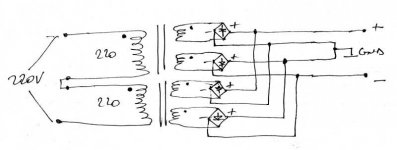
here it is
dots are for orientation - means that primaries must be in phase , and - secondaries must not be , but doesn't harm if they are in phase ;
how you'll check that :
1. be sure to include 1A slow blow fuse in line with mains while testing
2. use bulb (220V/25-40W is fine ) in line with mains
2 connect two primaries in series , do not connect anything at secondaries ; put AC voltmeter across one secondary ; power up - if you are measuring full expected voltage across sec . then pry. are in phase ; leave it as is - primaries are that way in phase
- if AC voltage is near 0 or 0 , change orientation of one primary ,and check again
same procedure for secondaries orientation check ; if you are not sure that you follow me with this ...... do nothing and ask again
edit: just a tip : if xformers are identical - it's almost always the case that same position/place/side connection eyelet is electrically identical on both ; meaning - left eyelet of primary is , say, start of winding on both xformers ; same logic for secondaries
but - to be sure - you must check voltages , to confirm proper phasing
Attachments
Last edited:
Excellent! Thank you very much Zen Mod!
I think it is now pretty clear to me how it should be done, especially with your sketch and description. I will ponder the circuit a little while just to be sure I’ve got it right and thanks for your encouragement to ask more questions.")
Kind regards
/Forsman
I think it is now pretty clear to me how it should be done, especially with your sketch and description. I will ponder the circuit a little while just to be sure I’ve got it right and thanks for your encouragement to ask more questions.
Kind regards
/Forsman
same procedure for secondaries orientation check ; if you are not sure that you follow me with this ...... do nothing and ask again
How do you carry out the orientation check for the secondaries? Interesting stuff.
Regards,
Chris
fit the bulb tester between the mains and the transformer under test.
If the bulb lights up there is something wrong.
If the bulb does not light up it is probably OK. If the bulb glows dimly then you have to find where the current is going.
You can deliberately wire the transformer wrongly to check that the bulb indicates correctly. Nothing will be damaged doing this test. That's the purpose of the bulb, to prevent damage.
How do you carry out the orientation check for the secondaries? Interesting stuff.
Regards,
Chris
will write later .....
How do you carry out the orientation check for the secondaries? Interesting stuff.
Regards,
Chris
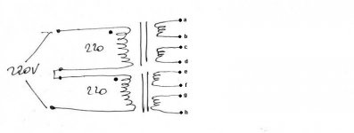
so - presume that we already made proper series connection of primaries , as written in my previous explanation ;
look at pic ;
for start - don't forget fuse and bulb; all secondaries are disconnected , in other words bare/naked ;
take care to power off always when you are doing any manual operation with connections , even if bulb will protect in case of shorts/miswiring on secondary side
let's say that expected voltage across each secondary is 18Vac
connect b&c ;power up ; measure AC voltage across a and d ; if you have 36Vac then ab & cd are in phase ; if not - switch position of c & d and repeat procedure ; when you have proper phase , mark eyelets/wires ;
disconnect b&c ; connect d&e ; power up ; measure Vac across c & f ; look for 36Vac ; then mark them .
disconnect d&e ; connect f&g ; power up ; measure across e & h ; look for 36Vac ; then mark them
I hope explanation is clear enough ; if any step in procedure became unclear , power off and think
better safe than sorry .
Attachments
Papa use that way in his FW amps ;
reason is simple - cleaner ground and prevented possible xformer buzz , in case of slightest un-symmetry of secondaries
Naim wakoos use same technique , in their amps , if I remember correctly
reasons are completely high fidelity - hard work for every little detail
result is cumulative
reason is simple - cleaner ground and prevented possible xformer buzz , in case of slightest un-symmetry of secondaries
Naim wakoos use same technique , in their amps , if I remember correctly
reasons are completely high fidelity - hard work for every little detail
result is cumulative
deliberately using more than one secondary winding each with their own diode bridges
One step further : more than one secondary with their own diode bridges, and more than one transformer per channel.
(for examples, see AMT Class A power amp models of Metronome-T)
It has been a while since I did the changes, so this is from an email I wrote back then:
BAGS
- Fix error ±
- Updated version number and date
- Added extra holes 120mm and 60mm apart the other way
- Size: 130x70 mm
BACO
- Increased size to 250x50
- Adjusted holes to 80mm and 5mm from board edge
- Updated version
- Deleted one set of diodes and moved the others in center
- Size: 250x50 mm
BASO
- Same as BACO
- Size: 250x50 mm
BACB
- Resized to 50x50mm
- Moved holes 5mm from edge
- Updated text
- Size 50x50 mm
BASB
- Resize to 50x60mm (difficult to get down to 50x50 due to elna silks)
- Moved holes 5mm from edge
- Updated text
- Changed the S wire routing
- Size 60x50mm
- Home
- Amplifiers
- Pass Labs
- Burning Amplifier BA-2