What would really make me happy is a photo of a heatsink which can do the job and, so that we can get some idea of its size, stand it next to something we would all recognise--like a barn door or something.
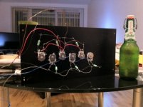
I've tested this heatsink from Birmingham Aluminium and it does the job
0.28 degrees per Watt
dimensions 400*200*40
it's definitely warm to the hand, takes maybe an hour before the temperature is fully stabilised, most of the way there in 30 minutes.
Attachments
Given a temperature rise of 30C
This can be x*?@! hot when ambient is 35°C.
I like to chose 20°C above ambient, it suits to every season without fingers burning.
I should have said "Suppose you can accept a temperature rise of 30°C..."
Of course acceptable heat sink temperature rise is a personal choice. Papa says about 55°C is decent. Each of us balance the cost of heat sinks and how big the amp must be to accommodate them and acceptable sink and junction temperatures. Often we reach different conclusions.
Where you live and whether you are air conditioned in the summer determine the spread between ambient and heat sink. When home in the summer I limit my home to a bit less than 25°C so I can accept a 30°C rise. Your home may be hotter or you may not want to have heat sinks so warm that you cannot touch them indefinitely. Adjust the rise and required heat sink to taste. If my son was allowed to set the indoor temperature I could almost get away without heat sinks.")
Of course acceptable heat sink temperature rise is a personal choice. Papa says about 55°C is decent. Each of us balance the cost of heat sinks and how big the amp must be to accommodate them and acceptable sink and junction temperatures. Often we reach different conclusions.
Where you live and whether you are air conditioned in the summer determine the spread between ambient and heat sink. When home in the summer I limit my home to a bit less than 25°C so I can accept a 30°C rise. Your home may be hotter or you may not want to have heat sinks so warm that you cannot touch them indefinitely. Adjust the rise and required heat sink to taste. If my son was allowed to set the indoor temperature I could almost get away without heat sinks.
No real reason why the amp should not run a little hotter than 55°C, that's only a comfortable rule of thumb that avoids that small children and pets don't burn their curious little fingers - high reliabilty is an added bonus
In many commercial amps heatsinks run a lot hotter and are still reliable.
Have fun, Hannes
In many commercial amps heatsinks run a lot hotter and are still reliable.
Have fun, Hannes
Not having done this before I can't answer on the bias current, I suppose I'll aim at 250mA, but the supply voltage will be 25V on each rail.
Is that 250mA per device or total?
Actually let me put it another way. If you have two of those heatsinks ie 40cm x 15.5cm x 4cm (one per channel) then you will have no issues dissipating 100W of heat per channel you could probably go as high 130W without issues.
Based on the 100W figure you can bias at 2A total per channel using +/-25V rails. Start with that then if you want more use the hand test as posted by Nelson/Zen Mod.
If you only have one of those heat sinks then you need to half the bias (ie 1A per channel total) then slowly increase using the hand test.
Last edited:
My heat sinks will then be 150 * 0.4 + 30 = 90 C which is 25 degrees higher than what Mr. Pass recommends (if I got it right).
Mr. Pass recommends 50 deg C for heat sinks.
/Forsman
Is that 250mA per device or total?
Thanks Melon Head,
Very useful. I'm not sure what is required to bias the circuit. Reading Nelson's instructions I get the impression that one measures across the 1 ohm source resistors of the output stage for voltage which equates with current. 250mV for 250mA.
Another question from this is during this test procedure what does one put across the speaker output terminals? Some sort of dummy load?
Best wishes,
Chris
........
Another question from this is during this test procedure what does one put across the speaker output terminals? Some sort of dummy load?
.....
nothing
you don't need load
nothing
you don't need load
I thank you. Excellent. Well sorted!
I've tested this heatsink from Birmingham Aluminium and it does the job
0.28 degrees per Watt
dimensions 400*200*40
highfieldrebel,
What was the heatsink model from Birmingham Alumimium?
Regards,
Chris
1510 HS
My plan was 4 pairs of FETs, 25 V rails, 0.5 A bias.
Heat to be dissipated is then 4*(25+25)*0.5 = 100 W
0.28 degrees/W * 100 = 28 degrees above ambient
so, 50ish degrees for the sink.
BTW, I have no connection with the supplier, but I would definitely deal with them again, very friendly and helpful.
Steve
check the manufacturers datasheet.Heat to be dissipated i...... 100 W
0.28 degrees/W * 100 = 28 degrees above ambient
When Delta T s-a is equal to the manufacturers specified figure AND the whole backplate is isothermal, then he guarantees their Rth s-a for their heatsink.
If Delta T s-a is different from the specification then the manufacturer usually gives correction factors to allow users to predict the Delta T s-a more accurately.
Your modeling missed out this procedure.
The correction factor could be anywhere between 1.0 and 1.5 for a Delta T s-a of 28Cdegrees.
Using a factor of 1.2 would increase Delta T s-a from 28Cdegrees to 33.6Cdegrees resulting in a prediction of Ts=33.6 + 28 =~61degC when Ta = 28degC, Tc will be higher.
There is another correction when the backplate is not isothermal. I have not seen any manufacturer giving this correction for some proportion of the backplate being cooler than the hot spot right next to the heating devices.
There is free software that does include both correction factors in the modeling.
It also takes account of location of the "hotspots". The version I have used is very good. I don't know how accurate it's predictions.
Last edited:
BTW, I have no connection with the supplier, but I would definitely deal with them again, very friendly and helpful.
Steve
Thanks Steve,
I was on to them this morning and you are right, they are very friendly.
I have been looking through Nelson's BA-2 advice and he says that the bias of 250 mA results in dissipation of about 6 wattts per transistor.
If one is using six then surely the power dissipation is going to be 36W not 75W which is the figure I have been using up to now?
I have two old Thorens, Restek E3 monoblocks which I thought I could use for a couple of Nelson Monoblocks. Only one of the two heatsinks in each case has been drilled. Any one know what sort of heat these were designed to dissipate?
Regards,
Chris
That's right on the dissipation, 24V * 0.25 A is 6 W per FET, 3 pairs is 36 total.
If you don't find info on your heatsinks, you could run a test. I found old, high power transistors in an old amp, attached them to the heatsink and ran a high current through them using my BA-2 PSU. (I put a 0.5 Ohm power resistor on the emitter, and controlled the current using the voltage on the base.). Try a current and see how well the sinks work.
Andrew, that's interesting on the calculations, I figured there would be some correction necessary. I ran the test and the sink was about 55, with 20 ambient. So a rise of 35 instead of 28 degrees, 25% higher. In the actual amp, I'll use 8 rather than the 6 FETs used in my test, should spread the heat a small bit better.
One thing that caught my eye was your use of 30 as ambient, is this to account for the heat the PSU is throwing off and the poor air circulation in the case?
Ta=28degC was chosen for an external heatsink in summer weather that is sufficiently cool not to require air-conditioning.One thing that caught my eye was your use of 30 as ambient, is this to account for the heat the PSU is throwing off and the poor air circulation in the case?
If you know that Ta=28degC is not appropriate then insert your value for Ta.
In Scotland I will never install air conditioning. Based on past experience, inside house temperatures rarely exceed 25degC and even less often exceed 28degC.
I’ve found four transformers specified to 115 or 230 V primary and 2*35 V secondary, 2-300 VA (aprox). I´m pretty novice when it comes to electronics and therefore I might ask very naive questions.
Could I make these transformers work in the PSU for the BA2 by connecting the primarys in series? Would that give me a secondary AC voltage of 35/2=17.5 V? I have AC 230 V in our net and I´m a bit confused about the wiering of the primarys of the transformer.
Kind regards
/Forsman
Could I make these transformers work in the PSU for the BA2 by connecting the primarys in series? Would that give me a secondary AC voltage of 35/2=17.5 V? I have AC 230 V in our net and I´m a bit confused about the wiering of the primarys of the transformer.
Kind regards
/Forsman
Last edited:
- Home
- Amplifiers
- Pass Labs
- Burning Amplifier BA-2