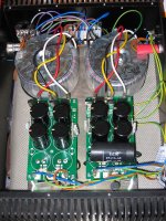
Here are some views of the completed power supply. To test without the amp what do people suggest. I'd like to see how much current and voltage I have so what about some light bulbs?
Regards,
Chris
Regards,
Chris
Attachments
OK I seem to be getting 25.3V on each rail.
I have read here that some of you have had some very hot thermistors but after 30mins since I turned the power supply on I can not feel the CL60s getting warm at all.
The diodes haven't even warmed up yet either. Mind you they are rated at 30A, 1200V each.
Regards,
Chris
I have read here that some of you have had some very hot thermistors but after 30mins since I turned the power supply on I can not feel the CL60s getting warm at all.
The diodes haven't even warmed up yet either. Mind you they are rated at 30A, 1200V each.
Regards,
Chris
OK I seem to be getting 25.3V on each rail.
I have read here that some of you have had some very hot thermistors but after 30mins since I turned the power supply on I can not feel the CL60s getting warm at all.
The diodes haven't even warmed up yet either. Mind you they are rated at 30A, 1200V each.
Regards,
Chris
that's logical
you don't have power draw from PSU and everything must stay cold
CL60s in the primary feed? These pass mains Live. DO NOT touch them.OK I seem to be getting 25.3V on each rail.
I have read here that some of you have had some very hot thermistors but after 30mins since I turned the power supply on I can not feel the CL60s getting warm at all.
Well I'm driving a couple of 100watt light bulbs on each power source and they are warm but no sign of burning. I'm going to have to wait for the BA2 boards before I can really put things to the test.
Regards,
Chris
You don't have to wait for the BA2 boards, you can test it using a dummy load...
This is just my approximation based on your test set-up, I presume the load light bulb is rated 100W ,230-240 volts, connected to your power supply output ~25Vdc, By deduction, bulb would draw ~10Watts, producing maybe a little glow in the bulb, The BA2 is expected to draw 300W
 at full blast bias, stereo. I would suggest to find a DC halogen lamp rated at 100W-150W (or equivalent say two 12 volts 50w-75w connected in series ) and connect as load to give your PSU a really good workout..
and also I'm a little bit worried with your air cooled diodes.
Last edited:
Chris,
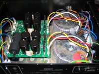
Your power supply looks just fine from here, but IMHO it should all be turned 90 degrees. At the moment the transformers are right next to where you are going to put one of the amp boards. The other side is OK, but you are likely to have hum in that one channel where ac is going into the transformer , and the transformer is spewing out all kinds of bad electro-magnetic stuff. So it would be best to have both transformers at the front or rear of the case, and keep the power supply boards a couple inches from the amp boards also. It seems to me that you can do this, and since you are waiting for the boards could address it now..
I see that you could have the transformers side to side, and the power supply boards side by side, right in front of them. Or the transformers in a row down the middle and a power supply board on each side of them. Symmetry is good, then each channel operates under the same conditions.
The diodes might need to be on a small heatsink also, but I'm not sure that their metal backs are live or not, you may need insulators if you attach them to the same sink..
Mark
Last edited:
Mark,
Thanks for taking the trouble to think the design through. The case wasn’t as big as I had hoped when it arrived (and the transformers arrived) and therefore I decided to keep this as a power supply only. I have some leads coming out of the back which will supply the separate audio amp case. It is a shame because as you can see there are some nice heatsinks on the power supply case. Of course nothing is set in concrete and I could modify the design along the lines you suggest.
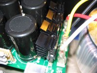
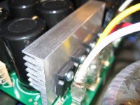
I have now wired up two 12V, 20W halogens in series, and put a pair of these on each rail making a total of 80W on one power supply transformer. The diodes became hot within a couple of minutes, too hot to touch so I have put on some ‘Indian Headress’ heatsinks. I ran the rig for about half an hour and the heatsinks got hot but not so hot that I couldn’t keep my finger on them for about ten seconds. I’m going for the three pairs of mosfets rather than the six pairs per channel so are things going to get hotter?
Regards,
Chris
Thanks for taking the trouble to think the design through. The case wasn’t as big as I had hoped when it arrived (and the transformers arrived) and therefore I decided to keep this as a power supply only. I have some leads coming out of the back which will supply the separate audio amp case. It is a shame because as you can see there are some nice heatsinks on the power supply case. Of course nothing is set in concrete and I could modify the design along the lines you suggest.
I have now wired up two 12V, 20W halogens in series, and put a pair of these on each rail making a total of 80W on one power supply transformer. The diodes became hot within a couple of minutes, too hot to touch so I have put on some ‘Indian Headress’ heatsinks. I ran the rig for about half an hour and the heatsinks got hot but not so hot that I couldn’t keep my finger on them for about ten seconds. I’m going for the three pairs of mosfets rather than the six pairs per channel so are things going to get hotter?
Regards,
Chris
I’m going for the three pairs of mosfets rather than the six pairs per channel so are things going to get hotter?
Regards,
Chris
Hi Chris
I think you're running 1.6 A at the moment, if you divided this by three, just over 0.5 A per pair of power diodes, or twice as high as the original design document, so no problem.
Steve
I've tried both of these heatsinks this afternoon and both run too hot to touch after about 10minutes.
Perhaps these large HexFreds run hotter than say other designs.
I'm going to try a diode bridge as per Nelson's instructions, 35A 200V and see if this starts glowing.
Regards,
Chris
Perhaps these large HexFreds run hotter than say other designs.
I'm going to try a diode bridge as per Nelson's instructions, 35A 200V and see if this starts glowing.
Regards,
Chris
Attachments
Hi Backbones,
Very cool!! your construction notes / picture would help a lot of people interested in building the BA amps. Thanks,
Can you please give a brief description of your psu design. Is it a dual mono design? or 1 transformer for each +24v and -24v rail? What sort of bias value or output power are you aiming for?
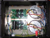
Its probably a good idea to bolt the diode bridges on the chassis floor. As per picture above, it is likely that heat coming from the diode heatsink will slowly cook your first caps, altering its electrical characteristic , in the long run will produce psu noise..
Very cool!! your construction notes / picture would help a lot of people interested in building the BA amps. Thanks,
Can you please give a brief description of your psu design. Is it a dual mono design? or 1 transformer for each +24v and -24v rail? What sort of bias value or output power are you aiming for?
Its probably a good idea to bolt the diode bridges on the chassis floor. As per picture above, it is likely that heat coming from the diode heatsink will slowly cook your first caps, altering its electrical characteristic , in the long run will produce psu noise..
reytnz,
It is dual mono and as for bias value I will have to cross that bridge when I come to it ie, when the pcbs have arrived and components fitted. I'm not that confident about that stage but this forum will be crucial.
Over the last 4 hours I have removed the HexFreds (I must get a decent desoldering tool) and have fitted on one of the power supplies a set of 20A, 200V Schottky diodes with the same 'Indian Headress' heatsinks as in the photo above. They have been powering the same light bulbs as before for 20 minutes and the heatsinks are just warm running to mildly hot to the touch ie, they are running a darn site cooler than the HexFreds.
Interesting!
Regards,
Chris
Sorry I forgot the brief description of the power supply.
It is identical to Nelson's design. The caps are M-Lytic 10000uF 63V AG and the 10uF caps are Ampohm 600V polyprops. The pcbs on which everything is attached is from Avondale Audio in the UK which sells a not disimilar power supply board to Nelson's design.
The transormers are custom built by Canterbury Windings in the UK fitted with a static shield and two secondary outputs 18-0-18V.
Last edited:
Backbones,
If you stick with the original BA2 design, 150W is the max load you need out of your transformer-mono. Test you psu close to 150W power draw, so you have more flexibility on your bias selection later on. Mr. Pass designed his amps to last at least 20 years, as per Passlab's manual. With the above set-up, with the heatsink near the caps and heat venting towards it, the heatsink will act like a slow cooker for your caps. Most caps breakdown due to heat.
If you stick with the original BA2 design, 150W is the max load you need out of your transformer-mono. Test you psu close to 150W power draw, so you have more flexibility on your bias selection later on. Mr. Pass designed his amps to last at least 20 years, as per Passlab's manual. With the above set-up, with the heatsink near the caps and heat venting towards it, the heatsink will act like a slow cooker for your caps. Most caps breakdown due to heat.
Why not use those inexpensive square bridge diodes ( the ones that have a metal casing ); 2 pieces per channel, to better share the load. I think these ordinary bridges is well suited to be use in these application, it is optimized to switch the line ac (50hz). Those high speed ones perform better in high frequency application as in SMPS. Apparently 2-bridge diode power supply sounds better. Have a look at the F5 amp actual photo in the web.
- Home
- Amplifiers
- Pass Labs
- Burning Amplifier BA-2