Thanks Jim,
I knew it was a simple formula. Its been almost 18 years since I did electronics theory in the Air Force, my memory is getting a little rusty. Ask my kids they get smarter everyday and I get dumber.
So if I did my calculations correctly for the 3 pair deep output I'm drawing approx. 2.25 amps a channel, which is under Papa's 3 amp recommended maximum. Reading the construction notes he designed it for 1.5 amps a channel, but says up to 3 is okay. Shooting the sinks by the Mosfets with a temp gun gives me about 65 C and the tips of the fins are about 47 C. I may back it down just a bit so its not stressed at all.
Chad
250 x 6 deep= 1,5A with 1 Ohm,
With 0,47 Ohm you have to double the Volt values 350 x 2= 7ooA x 3 deep= 2,1A. I hope I made no fault, I always panic a little bit with mathematics.
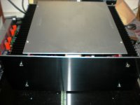
You seem to have big heatsinks!
I tried axon, I liked silmic more.
Of cause I made a fault. Corrected!
I give up I cannot count any more ( have a cold, lying in bed )
....!
With 0,47 Ohm you have to double the Volt values 350 x 2= 7ooA x 3 deep= 2,1A. I hope I made no fault, I always panic a little bit with mathematics.
You seem to have big heatsinks!
I tried axon, I liked silmic more.
Of cause I made a fault. Corrected!
I give up I cannot count any more ( have a cold, lying in bed )
....!
Last edited:
....( have a cold, lying in bed )
....!
boiled Vino or Rakija .........
I presume olde Schwabische recipe is known to you
")
Not to worry, we have put the production order in: BA-1's, 2's, F-4's F-5's
Thats great!
Russellc
In the BA2 article, Mr. Pass mentioned, one way of correcting the IR P-Channel Mosfet distortion is to use a different mosfet. I am half way in the build and seriously considering using the 2SK1530 and 2SJ201 for output devices instead of the IRF's, for it's very good trace as shown by EUVL in another thread and for its robust apperance. The only problem is, I don't know how to implement this. Can somebody show how it's done, please ...What part to change / adjustments to get the optimum performance out of the Toshiba's? Any input is greatly appreciated, thanks in advance. Rey
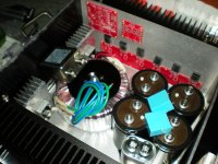
I’m sure I’m not the only one waiting for the BA-2 boards but that hasn’t stopped my building the power supply side of the amp. Faced with a variety of options—I’m following Nelson’s design—on the component side I thought it might be interesting to listen to some of the variations mentioned on this forum.
I managed to find some 50V 10uF Elna Silmics in the end and I added these to a collection of 10mH wire wound chokes that I thought I might use on the ‘pi-filter’ side as well as the 10uF Ampohm polypropylenes.
I decided to use my trusty PURE digital radio and its 12V supply as mentioned before which consisted of toroid transformer, HexFred diodes, 22000 uF Mlytic, LM338 voltage regulator followed by a Panasonic 22000uF cap. Incidentally, I’m using diodes on the LM338 to control the voltage.
So this was then the supply into Nelson’s design using a pair of Mundorf Mlytic AG, 10000uF caps (about £20 each so not cheap) with the four 1ohm resistors in parallel. The final set of caps were changed between the AmpOhms and the Silmics.
Moving from the native power supply on its own, and then listening to it through the BA-2 design was like moving from a smoky nightclub to a minimalist office. The warm glow of instruments was replaced with a clearer perspective where instruments were more clearly defined. Leading edges were clearer and sharper but not annoyingly so. Background noise was reduced and voices were clearer. Dynamics were improved also.
With the second board I put in the Elna Silmics instead of the AmpOhms and this time the results were less of an improvement over the source power supply on its own and in fact the difference was small. The sound retained a sense of warmth but it had the affect of again making the images seem less distinct. Leading edges remained relaxed and less well defined than with the AmpOhms and I actually felt voices were clearer on the native power supply without the BA-2 additions.
I thought the AmpOhms were the clear winner here so I decided to stick with them and add the Choke to the four resistors in parallel. There was a further clearing of background noise here with a darker background and even better defined images, which I initially liked but then found they were beginning to sound a little too sharp and mechanical. I didn’t have the energy to try just the choke instead of the reistors but perhaps next time.
Best wishes,
Chris
Hi Reyntz,
Do you think you need that much heatsink for the diode bridges? You're making me feel inadequate.
Regards,
Chris
Hi Chris ,
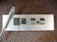
All the current the amp will be consuming will pass through these bridge diodes, one bridge supplying half of each channel. I would like to run mine about 3 amps per channel or 1 amp per output devices x2 channel, that would mean 6amps continuous current draw through each bridges, approximately. I have them in a separate heatsink and not stick them to the main h/sink because I want the the output devices to have a uniform thermal characteristics, I actually feel the bridges heatsink is inadequate, still need to thermally couple it to the chassis floor.
Regard,
Rey
Last edited:
I’m wondering if these bridge diodes the really needs to be rated as high as 35 A. I have a couple that are rated 25 A 400 V. Will these be sufficient or must i get bigger ones?Hi Chris ,
All the current the amp will be consuming will pass through these bridge diodes, one bridge supplying half of each channel. I would like to run mine about 3 amps per channel or 1 amp per output devices x2 channel, that would mean 6amps continuous current draw through each bridges, approximately.
/Forsman
I’m wondering if these bridge diodes the really needs to be rated as high as 35 A. I have a couple that are rated 25 A 400 V. Will these be sufficient or must i get bigger ones?
/Forsman
I'm using 25A 800V garden variety, I think its more than enough with allowance for transient current.
Rey
- Home
- Amplifiers
- Pass Labs
- Burning Amplifier BA-2