Leaving a metal chassis unconnected is a absolute no-go! (see the previous post...)Should I put in a star ground attached directly to the chassis or leave the chassis unconnected in box 2?
This is what I would do. Connect the enclosure of box 2 directly to the mains-Earth. Connecting the encloure of box 2 to a second GND-star in box 2 will result in a loop, which may give you trouble. You should simply try this.Or perhaps connect the two enclosures but not connect the amp ground in box 2 to the chassis. [...]
Otherwise connect the GND-star of box 1 to the mains-Earth with a thermistor as recommended by NP.
This means you will have both GND and Earth running from box 1 to box 2 (plus voltage rails).
~ nightrush
Last edited:
These photographs have posed a question. I am in the process of putting a power supply together in a separate enclosure (box 1) but I hadn’t really thought of the grounding arrangements for the box containing the amp pcbs (box 2).
Should I put in a star ground attached directly to the chassis or leave the chassis unconnected in box 2? Or perhaps connect the two enclosures but not connect the amp ground in box 2 to the chassis.
Regards,
Chris
box 1 - chassis connected to safety gnd ; leave audio gnd floating ;
route all - PSU pos , audio gnd , PSU neg , safety gnd - from box 1 to box 2
connect safety gnd ditto to box 2 chassis
point where you connect audio gnd in box 2 - turret board or any other contact isolated from chassis is your general star ground point
then connect that star gnd to chassis (box2) via 10-30R NTC
you must remember that complete safety issues are covered only when both cases are connected via umbilical .
critical ( unsafe ) case is when you have box1 connected to mains , but unconnected umbilical to box 2 ; in that case there is no connection between safety gnd and power circuit/PSU . but I presume that you'll not using it in that way

don't forget bleeders across caps in box1 ; that way you'll not have sparks during connecting umbilical to box 2
Last edited:
That was quick, many thanks. Any talk of a live chassis is like phoning for the DIY Audio Forum emergency services, which is very reassuring. I’m often surprised how many mains electrical devices these days only have Live and Neutral mains connections and no earth wire, including my old Exposure CD player.
On a similar note the two transformers I ordered have electrostatic (ES) shields and therefore ground wires. Again my instinct is to connect these directly to the chassis earth or should I use a CL-60 between ES earth wire and chassis?
Regards,
Chris
On a similar note the two transformers I ordered have electrostatic (ES) shields and therefore ground wires. Again my instinct is to connect these directly to the chassis earth or should I use a CL-60 between ES earth wire and chassis?
Regards,
Chris
box 1 - chassis connected to safety gnd ; leave audio gnd floating ;
route all - PSU pos , audio gnd , PSU neg , safety gnd - from box 1 to box 2
connect safety gnd ditto to box 2 chassis
point where you connect audio gnd in box 2 - turret board or any other contact isolated from chassis is your general star ground point
then connect that star gnd to chassis (box2) via 10-30R NTC
you must remember that complete safety issues are covered only when both cases are connected via umbilical .
critical ( unsafe ) case is when you have box1 connected to mains , but unconnected umbilical to box 2 ; in that case there is no connection between safety gnd and power circuit/PSU . but I presume that you'll not using it in that way
don't forget bleeders across caps in box1 ; that way you'll not have sparks during connecting umbilical to box 2
ZenMod,
Can you tell me a little more about these 'bleeders'.
Regards,
Chris
")
ZenMod,
Can you tell me a little more about these 'bleeders'.
Regards,
Chris
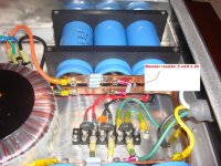
Chris,
Attached is a picture of the placement of the bleeder resistor.
As for power and earth grounding here is what I choose to due. Please if someone sees something wrong with this please voice your concerns. I want to be safe as I have kids in the house.
The power supply chassis is directly grounded to earth. From the chassis it goes to the power rail grounds buss bar thru a CL-60. Running from the power supply to the Amp chassis are 4 wires carrying the V+, V-, Power ground and a direct earth ground. In the amp chassis the earth is hooked to the chassis and nothing else. My star ground for the pcb grounds is on a buss bar connected to the power ground. My thinking was very close to Zen Mods but I wanted the power supply to have a chassis ground at all times incase it somehow got turned on without an amp plugged in. The amp is dead silent with no ground loops. I believe this fully protects both units but please let me know if you think different.
Attachments
In a combined amplifier and PSU with a metal chassis the Protective Earth (third wire in the mains cable) must be permanently connected to chassis.
The option to use a CL60 is for the Audio Ground to Chassis connection in lieu of a direct wire connection or a Disconnecting Network.
You do not put a CL60 in the PE to Chassis connection. You are not even allowed to rely on a soldered attachment for this permanent connection.
When you separate the PSU from the metal chassis Amplifier, then my interpretation is that the metal amplifier chassis must be permanently connected to PE. Again no CL60 in this connection.
The CL60 and Disconnecting Network can be used to connect all exposed conductive parts to Safety Earth. Safety Earth is an attachment to a PE protected Chassis.
I beleive he means using a 3-10W 2-2.2K resistor across positive to ground and from negative to ground across a set of caps in the power supply. When powered off, they will bleed down the voltage and discharge.
Doesn't Nelson already have a 2.2K, 3W resistor across the terminals as you describe, just after the rectifier? Would these not bleed down the voltage?
Regards,
Chris
Yes that is the bleed down resistor in Nelsons Power supply schematic. It can go any where in the DC voltage rails just needs to connect the DC voltage rails to the audio/ power ground. A capacitor will hold its charge for long time without them if no load is present, making for a bad day if you stick a hand in thinking everything is off. When I was in Air Force we would slightly charge a small capacitor then throw it to someone when they walked in shop door, your natural reaction was to catch it which was always good for a laugh. Another fun one was take the protection resistor out of a ground wrist/ankle strap, then when the person was wearing it we'ed take a Megger and connect it to the building ground system and send them a nice wake up shock. It would always take them a while to figure out why they where getting shocked.
Andrew described very clearly what I tried to say in my post. Both chassis have a direct earth ground and the Cl-60 connects the earth to power/audio ground in my power chassis.
Chad
Andrew described very clearly what I tried to say in my post. Both chassis have a direct earth ground and the Cl-60 connects the earth to power/audio ground in my power chassis.
Chad
Last edited:
Hopefully some one here can help me. I want to figure out how many amps of bias current I'm drawing. Does anyone know the formula for this? Papa states in his manual that the six deep pairs using 1 ohm resistors equals 1.5 amps when biased to 250mv across the resistor. I'm running three deep pairs using .47 ohm resistors at 350mv. I'm trying to get a better understanding how this all works. My heatsinks are running cooler than Papa's 55C max but I don't want to crank the bias any more till I know what I'm doing.
Did I mention how detailed this amp sounds. Can't wait to finish the BA-1 to compare the two. I also ordered some Axon caps to compare to the Elna silks.
Chad
Did I mention how detailed this amp sounds. Can't wait to finish the BA-1 to compare the two. I also ordered some Axon caps to compare to the Elna silks.
Chad
- Home
- Amplifiers
- Pass Labs
- Burning Amplifier BA-2